Device for measuring radiation and scattered light field three dimensional distribution

A technology of three-dimensional distribution and light field, which is applied in measurement devices, optical radiation measurement, coupling of optical waveguides, etc., can solve problems such as inability to accurately describe strong specular reflection peaks, small dynamic response range, limitations, etc., and achieve exposure Adjustable time, accurate measurement, avoiding the effect of influence

Inactive Publication Date: 2008-10-15
NORTHWESTERN POLYTECHNICAL UNIV
View PDF0 Cites 13 Cited by
  • Summary
  • Abstract
  • Description
  • Claims
  • Application Information

AI Technical Summary

Problems solved by technology

Kristin J Dana et al. used an off-axis parabolic mirror to reflect light scattered in different directions to the same direction and record it through a CCD camera, but it can only receive scattered light within a certain solid angle range in the hemispherical space, and due to the dynamics of the CCD The response range is small, and the saturation phenomenon will occur when the spatial distribution of light intensity fluctuates greatly, so that the measurement results cannot accurately describe the strong specular reflection peak
In addition, this method needs to be carried out in the laboratory, which limits the mobile field measurement

Method used


Image

  • Device for measuring radiation and scattered light field three dimensional distribution
  • Device for measuring radiation and scattered light field three dimensional distribution
  • Device for measuring radiation and scattered light field three dimensional distribution

Examples


Embodiment 1

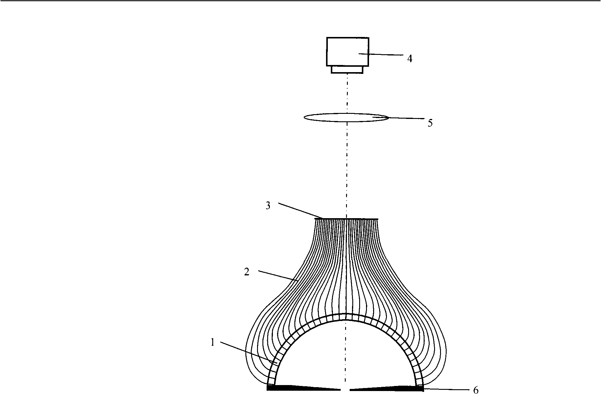
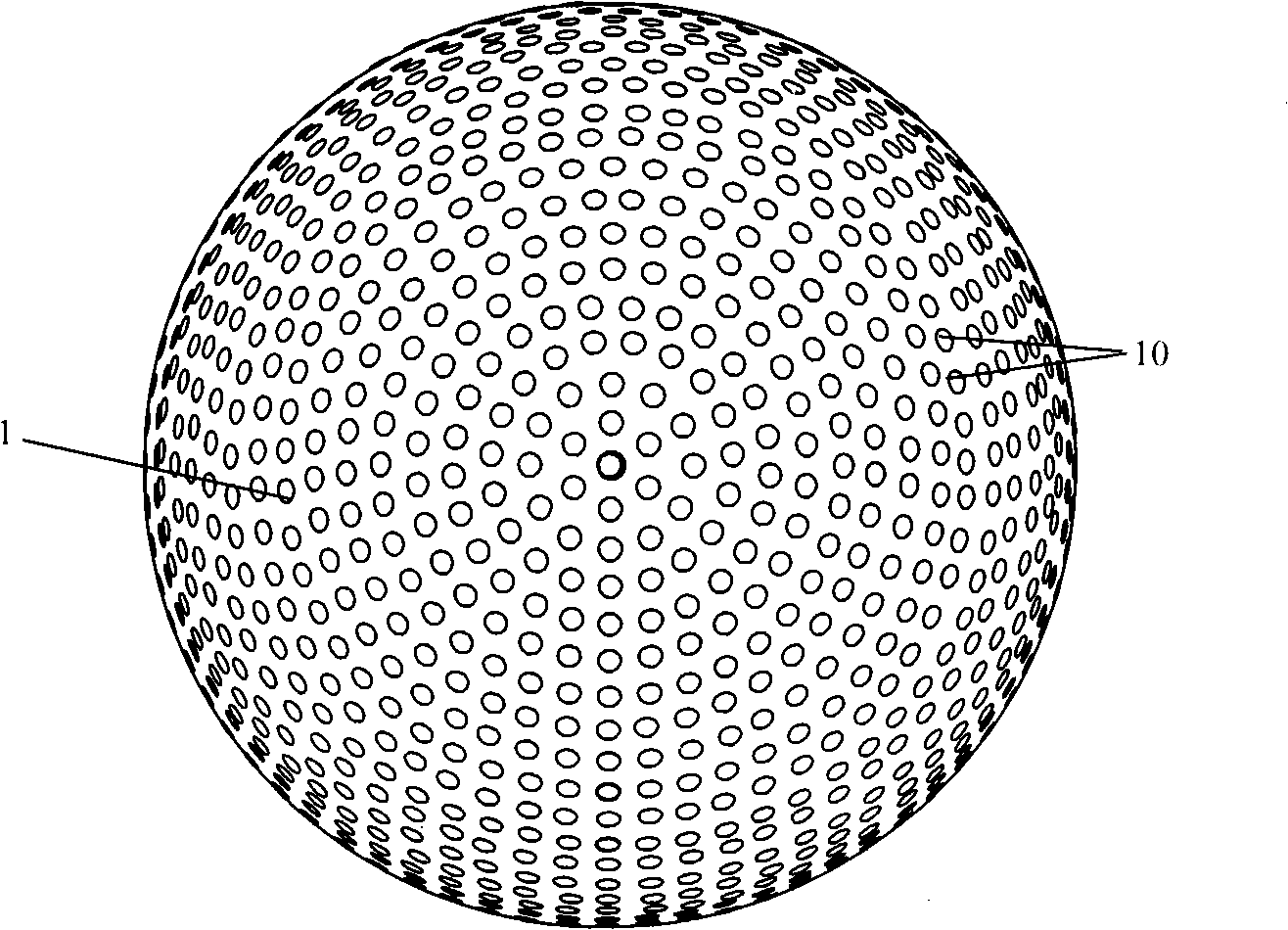
[0036] Embodiment 1: as figure 1The device for measuring the three-dimensional distribution of radiation light field includes a drilled hemispherical shell 1, an optical fiber 2, a drilled disk 3, an adjustable diaphragm 6 and an imaging system. All components are coaxially distributed along the main axis of the device, the adjustable diaphragm 6 is located at the bottom of the device, the drilled hemispherical shell 1 is located on the adjustable diaphragm 6, the lower surface of the adjustable diaphragm 6 coincides with the equatorial plane of the drilled hemispherical shell 1, And the center of the lower surface of the adjustable diaphragm 6 coincides with the center of the sphere of the drilled hemispherical shell 1 . The drilling disc 3 is located on the drilling hemispherical shell 1, and the two are connected by a number of optical fibers. The number of optical fibers is equal to the number of holes on the drilling hemispherical shell and the number of holes on the disc...

Embodiment 2

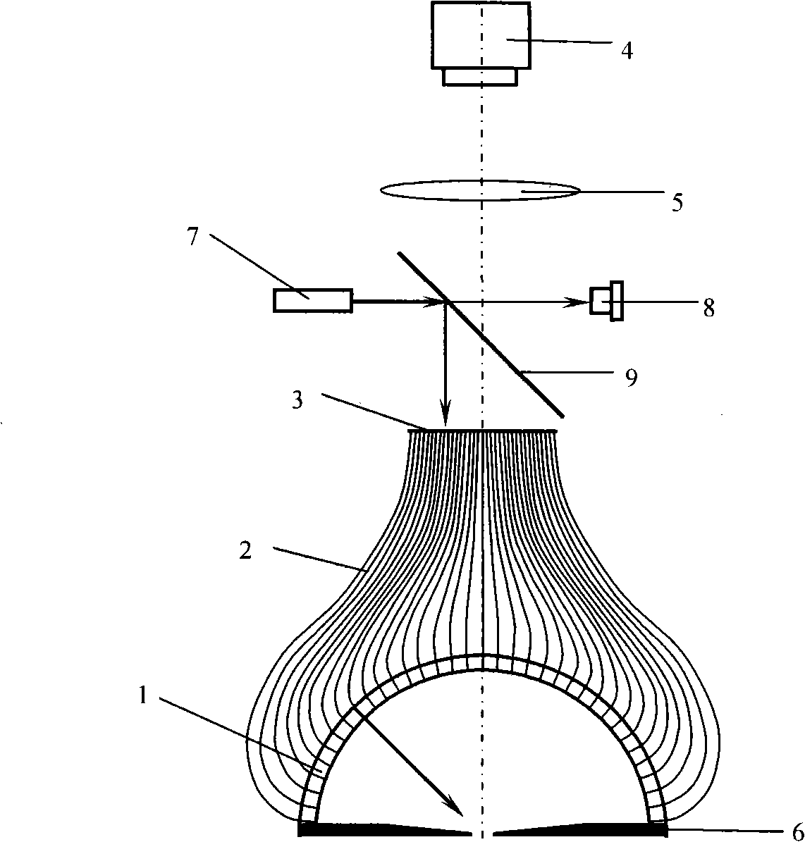
[0038] Embodiment 2: as figure 2 The device for measuring the three-dimensional distribution of the scattered light field on the surface of an object includes a drilled hemispherical shell 1, an optical fiber 2, a drilled disk 3, a light source power monitor 8, a beam splitter mirror 9, an adjustable diaphragm 6, a light source system and an imaging system . The structure of the device is based on the same structure as that of the device described in Embodiment 1, with the addition of a light source power monitor 8, a beam splitter 9 and a light source system. The beam splitter 9 is fixed between the disk 3 and the lens 5, and its normal line forms an angle of 45 degrees with the main axis of the device. Light source system 7 is made up of light source 18, lens 15, 17 and pinhole 16, and light source system 7 is positioned between disc 3 and lens 5, on the side of beam splitter 9, and its optical axis is perpendicular to the main axis of device, and light source system 7 As...


PUM


Abstract

The invention relates to a device for measuring three-dimensional distribution of a radiated and scattered optical field. The device is characterized in that: an adjustable diaphragm 6 is positioned on the bottom of the device; a drilled semispherical shell 1 is positioned on the adjustable diaphragm 6; a drilled disc 3 is positioned on the drilled semispherical shell 1; the drilled disc 3 and the drilled semispherical shell 1 are connected by a plurality of fibers; a lens 5 is positioned on the disc 3; a CCD camera 4 is positioned on the lens 5; a beam splitter mirror 9 with 45 degree angle between a normal line and a main shaft of the device is fixed between the drilled disc 3 and the lens 5; a light source system 7 is positioned on one side of the beam splitter mirror 9 ; and a light source power monitor 8 coaxial with the light source system is positioned on the other side of the beam splitter mirror 9. The device has the advantages that: the fibers and the area array CCD camera can rapidly measure the spatial distribution of a light source radiation optical field or a scattering optical field of the object surface; in the process of the optical scattering measurement, the light source power monitor is utilized to carry out real-time monitoring to the output power of the light source, thereby avoiding the influence of the light source output stability on a measuring result.

Description

technical field [0001] The invention relates to a device for measuring the three-dimensional distribution of radiation and scattered light fields, in particular to the field of measuring the distribution of three-dimensional radiation and scattered light fields by means of optical fiber transmission and through an array detector. Background technique [0002] The distribution of scattered light field on the surface of an object can be described by the bidirectional reflectance distribution function (BRDF). BRDF records the reflection distribution of the surface of the object to the incident light in different directions at various angles. It is a multivariate function, and the measurement process is complicated. [0003] There are two main types of existing radiation and scattered light field distribution measurement methods: one is to use one or more photodetectors to perform two-dimensional or one-dimensional scanning above the surface of the sample to be measured, and det...

Claims


Application Information

Patent Timeline
IPC IPC(8): G01J1/00G01J1/04G02B6/32G02B5/00
Inventor 赵建林任驹
Owner NORTHWESTERN POLYTECHNICAL UNIV
Why Eureka
Try Eureka