Single-phase heat drive heat-transfer element and its working medium loading method

A heat transfer element and working medium technology, applied in the direction of indirect heat exchangers, lighting and heating equipment, etc., can solve the problems of inaccurate working medium volume, small pipe fittings that cannot be produced, and cannot work

Inactive Publication Date: 2008-10-15
李建民
View PDF0 Cites 7 Cited by
  • Summary
  • Abstract
  • Description
  • Claims
  • Application Information

AI Technical Summary

Problems solved by technology

[0007] 1. The manufacturing methods of heat pipes can be divided into two categories. One is the vacuum method, which requires vacuum equipment, which consumes energy and time. The second is the heat exhaust method, which cannot accurately control the amount of working medium. It is limited to Manufacture of industrial heat pipes
[0008] 2. The sealing technology adopts the cold welding method for the vacuum pumping method. The only material that can be used for the tuyere is copper. Other metals are not suitable for this method. Therefore, it is limited that the heat pipe must use high-cost copper as the shell material, so Increased the cost of the heat pipe; In addition, for the heat exhaust method, due to the use of pins driven into the seal and then additional welding technology, the process cannot guarantee the overall quantity of working medium, quality and performance, and the main problem of this method The reason is that only large pipe fittings can be produced by this method, and small pipe fittings cannot be produced at all.
[0009] 3. Internal anti-corrosion problem: The working medium used may react with the material of the cavity, which reduces the vacuum degree, thus reducing the performance of the heat pipe, but eventually fails to work, so the life of the heat pipe is short and cannot be suitable for industrialization requirements.
[0010] Due to the technical defects of the existing heat pipe technology, the development of the heat pipe technology is hindered, and the heat pipe technology cannot be widely used.
[0011] The technology of using the internal working medium of a closed strong body for heat transfer is also used in the fields of air conditioning and refrigeration. It needs to work under the compressor to circulate normally, which consumes electric energy

Method used


Image

  • Single-phase heat drive heat-transfer element and its working medium loading method
  • Single-phase heat drive heat-transfer element and its working medium loading method
  • Single-phase heat drive heat-transfer element and its working medium loading method

Examples


Embodiment Construction

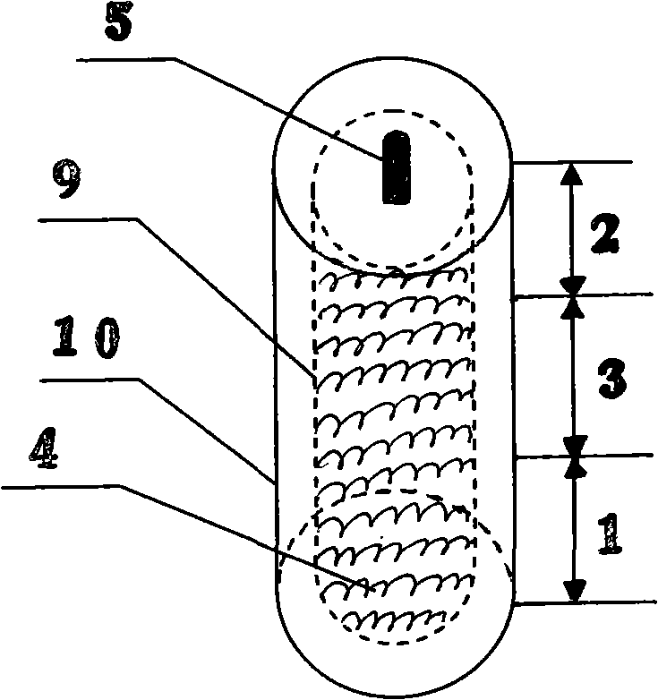
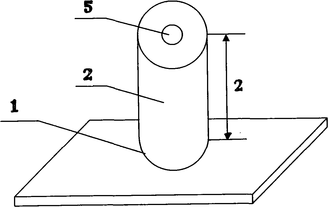
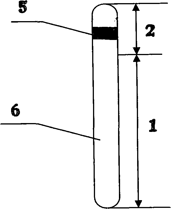
[0078] Basic Multiphase Heat Transfer Elements

[0079] Please refer to figure 1 , a carbon steel pipe with a diameter of 38MM and a length of 1M. The upper and lower ends of the pipe are sealed to form a cavity. Aluminum, whose thickness is thicker than the rare earth aluminum inside, is mainly used for anti-corrosion and heat conduction, and aluminum has higher heat conduction performance than carbon steel; inside the cavity, on a sealing surface of the tube, a one-way valve is processed, Use a one-way valve to fill the carbon dioxide gas into the cavity, and the weight of the filling is 300 grams. The solids are: 10 grams of copper with a particle size of 0.001mm, and 3 grams of copper oxide with a particle size of 0.01mm. 100 grams of aluminum with a particle size of 0.3 mm. This constitutes the basic multiphase heat conducting element. Working temperature range: 10-130°C, working pressure range: 1-15MPa. When the working temperature is 31 degrees and the pressure is 7...


PUM


Abstract

The invention provides a multiple-phase thermally driven heat transfer element. The heat transfer is realized by adopting the working medium single phase inside a sealed cavity body. At least one part of the cavity body is a heat absorbing end (part); at least the other part of the cavity body is a heat discharging end (part). In the heat transfer process, the working medium inside the cavity body keeps at least two-phase or multiple-phase composite heat transfer flow body; in the two-phase operation, the heat transfer is realized by keeping a way of other two phases such as solid and liquid, which is different from the vapor-liquid phase-change circulation of the prior heat pipe; meanwhile, the heat transfer can be also realized by three phases or more phases to realize the transfer of the heat energy; in the process of transferring the heat energy, only the heat energy provided by the heat source can realize the heat energy transfer without consuming the external energy.

Description

technical field [0001] The invention relates to heat transfer elements, including heat transfer, heat dissipation, heat transfer, heat collection, heat storage and other fields of heat conduction and heat exchange, and specifically relates to the heat transfer of a working medium in a closed cavity, and the working medium is in a multi-phase The heat transfer element for heat transfer in the state, and the filling method of its working medium. Background technique [0002] Using heat transfer medium to transfer heat is the most common way of heat transfer, that is, to use heat transfer medium to absorb heat at the heat source, and make the heat transfer medium after absorbing heat release heat in the heat release device or heat release end, and reach the hot purpose. The heat transfer medium flows as a closed system. This heat transfer method is widely used in industrial fields as well as civil and industrial equipment. [0003] The heat conduction process includes all pr...

Claims


Application Information

Patent Timeline
Patent Type & Authority Applications(China)
IPC IPC(8): F28D15/00
Inventor 李建民
Owner 李建民
Why Eureka
Try Eureka