
Method and apparatus for removing SO3 from flue gas

A flue gas, ammonia gas technology, applied in separation methods, chemical instruments and methods, dispersed particle separation, etc., can solve the problems of high process cost and uneconomical, increase the cost of large equipment, and reduce engineering costs and maintenance costs. The effect of preventing corrosion

Inactive Publication Date: 2008-10-15
浙江菲达环保科技股份有限公司
View PDF0 Cites 7 Cited by
  • Summary
  • Abstract
  • Description
  • Claims
  • Application Information

AI Technical Summary

Problems solved by technology

[0004] SO in the method of increasing flue gas temperature 3 Easy to form SO in flue gas 3 Acid mist, due to SO 3 The content is related to the acid dew point temperature of flue gas, SO 3 The higher the acid content, the higher the acid dew point temperature, and the flue gas discharged from the secondary discharge must be kept above the dew point temperature, so a large amount of energy is required to increase and maintain a high flue gas temperature, and there are special requirements for the structure and materials of the equipment, and the process cost is high not economical
Replacing equipment in advance or using corrosion-resistant alloy equipment will require a lot of equipment cost investment

Method used

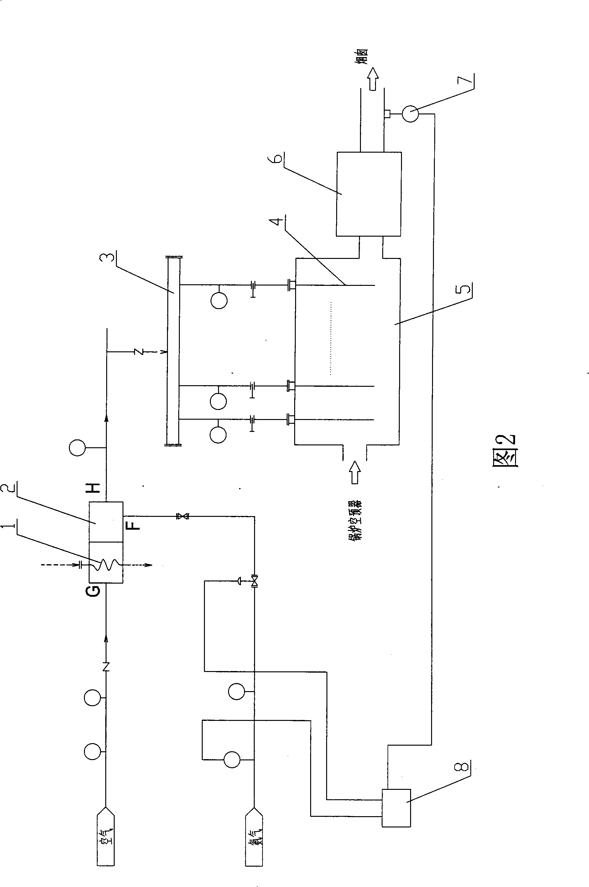

Image

  • Method and apparatus for removing SO3 from flue gas
  • Method and apparatus for removing SO3 from flue gas
  • Method and apparatus for removing SO3 from flue gas

Examples


Embodiment Construction

[0025] refer to figure 1 , a SO removal from flue gas 3 method, including the following steps:

[0026] Ammonia dilution 11: The air is boosted by the blower, heated by the air heater and flows into the mixer. The ammonia gas evaporated from the liquid ammonia is metered into the mixer. In the mixer, ammonia is mixed and diluted with hot air, and the explosion of ammonia gas is controlled. Within the limit; the mixer used is a co-directional and downstream mixing structure, and is equipped with a turbulent baffle.

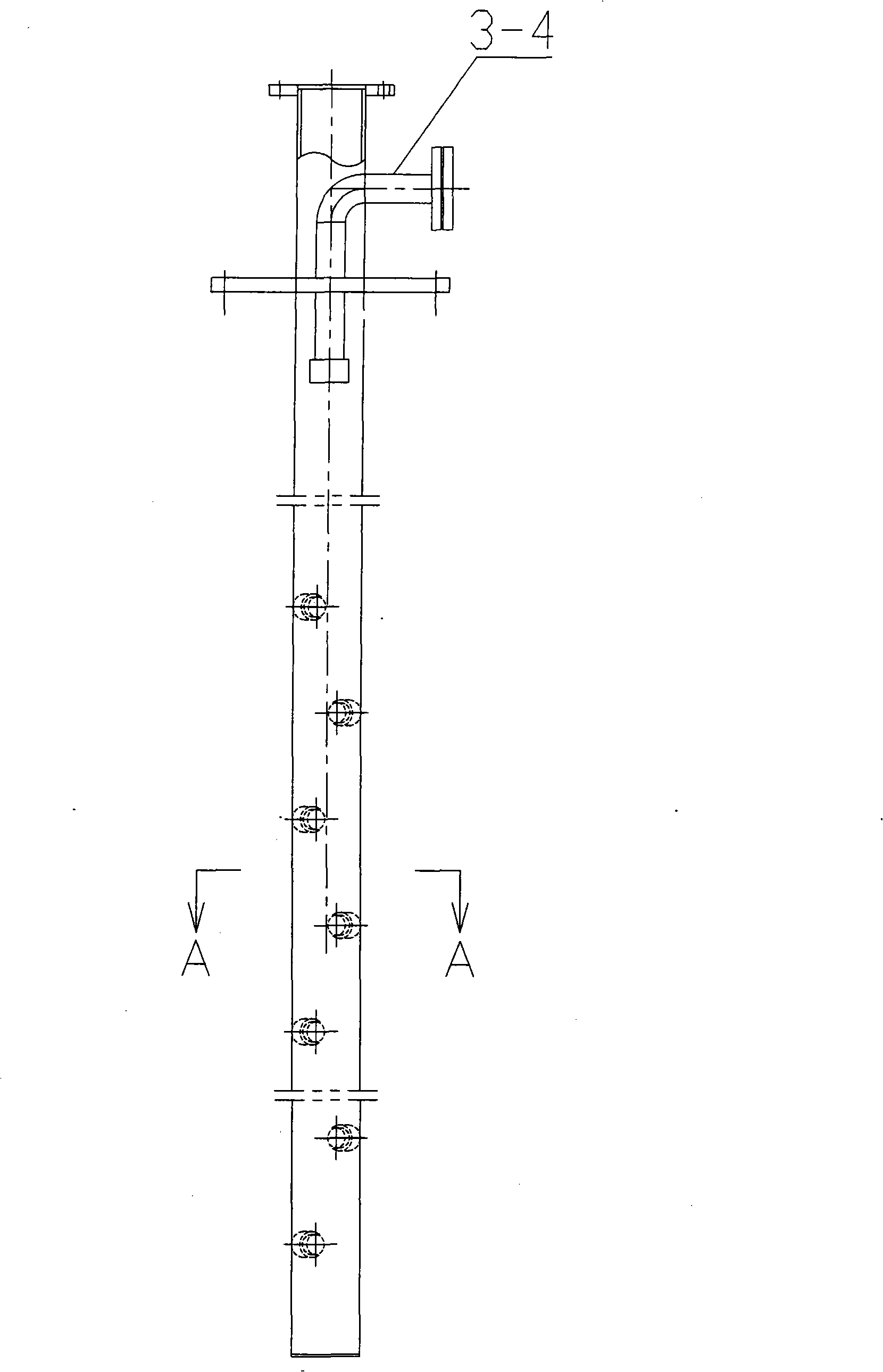
[0027] Ammonia injection injection 12: The mixed and diluted uniform ammonia gas is evenly injected into the flue through the ammonia injection injection system, and mixed with the flue gas, ammonia and SO in the flue gas 3 Reaction to remove SO 3 , remove SO 3 The final flue gas enters the flue gas system equipment; the ammonia injection injection system consists of an ammonia injection distribution main pipe and multiple nozzle pipes installed side by side. T...


PUM


Abstract

The invention discloses a method for removing SO3 from smoke gas which comprises the steps such as ammonia passing and dilution, ammonia injection and emission, residual ammonia detection, ammonia content adjustment, etc. The invention also discloses a device for removing the SO3 from the smoke gas, which comprises a mixer, an ammonia injection and emission system, a flue, smoke gas system equipment, and a control center. The mixer is provided with an ammonia gas inlet, an air inlet and an outlet; an air boiler is arranged at the air inlet, and the outlet is connected to an input end of the ammonia injection and emission system; an output end of the ammonia injection and emission system is inserted in the flue; a residual ammonia surveymeter is arranged on the rear end of the flue after the rear end of the flue passes through the smoke gas system equipment; the residual ammonia surveymeter is connected to the control center which is connected to the front end of the ammonia gas inlet. In the method, ammonia gas reacts with the SO3 in the smoke gas to remove the SO3, the residual ammonia detection is performed before the smoke gas is discharged, and the quantity of ammonia supply is adjusted according to the leak amount of the ammonia in the smoke gas, so as to keep the ammonia emission within bounds. The method can effectively remove the SO3, avoiding eroding the smoke gas system equipment, and lowers the cost.

Description

【Technical field】 [0001] The invention relates to an environmental protection process and device, in particular to a method for removing SO from flue gas 3 method and device. 【technical background】 [0002] A large amount of exhaust gas discharged from boilers or thermal power plants that use coal or oil as fuel contains SO 3 substances, to prevent SO 3 Direct emission causes environmental pollution, and the flue gas needs to remove highly corrosive and harmful SO before emission 3 substance. [0003] Currently, removal of SO in flue gas avoids 3 Corrosion methods mainly include increasing flue gas temperature, replacing equipment in advance, or using corrosion-resistant alloy equipment. [0004] SO in the method of increasing flue gas temperature 3 Easy to form SO in flue gas 3 Acid mist, due to SO 3 The content is related to the acid dew point temperature of flue gas, SO 3 The higher the acid content, the higher the dew point temperature of the acid, and the flue ...

Claims


Application Information

Patent Timeline
Patent Type & Authority Applications(China)
IPC IPC(8): B01D53/50B01D53/76
Inventor 周钓忠舒英钢葛介龙李文勇张佩芳张永顾晖斯洪良陈招妹崔盈
Owner 浙江菲达环保科技股份有限公司
Learn More