
Tridimensional distributed type material stream circulating method and ventilated synthetic energy-saving method

A distributed and material technology, applied in botany equipment and methods, ventilation systems, space heating and ventilation, etc., can solve the problem of direct discharge of hot air or hot and humid air, high investment and technical costs, and restrictions on large-scale development, etc. problems, to achieve the effect of reducing maintenance workload, reducing investment and operating costs, and reducing equipment investment

Inactive Publication Date: 2008-10-08
张玉良
View PDF0 Cites 12 Cited by
  • Summary
  • Abstract
  • Description
  • Claims
  • Application Information

AI Technical Summary

Problems solved by technology

On the other hand, a large amount of hot air or hot and humid air generated after ventilation is often directly discharged
However, the utilization of green resources such as wind resources and solar energy has been constrained by their high investment and technology costs. At present, there is no technology that can concentrate and comprehensively utilize these low-density energy sources.
In addition, when using porous materials such as copper foam as the heat and mass transfer medium with the fluid, as the specific surface area and the overall volume of the foam material increase, the resistance of the fluid passing through the foam material also increases significantly, and the increase in power consumption restricts large-scale development

Method used


Image

  • Tridimensional distributed type material stream circulating method and ventilated synthetic energy-saving method
  • Tridimensional distributed type material stream circulating method and ventilated synthetic energy-saving method
  • Tridimensional distributed type material stream circulating method and ventilated synthetic energy-saving method

Examples


Embodiment 1

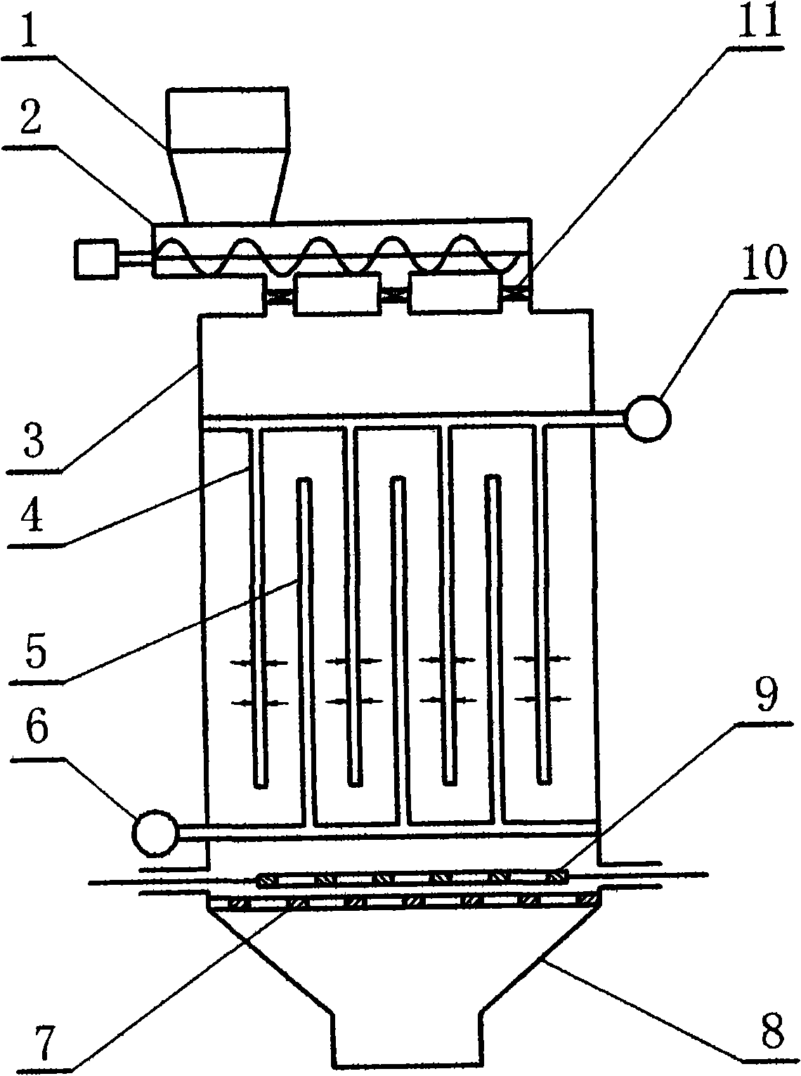
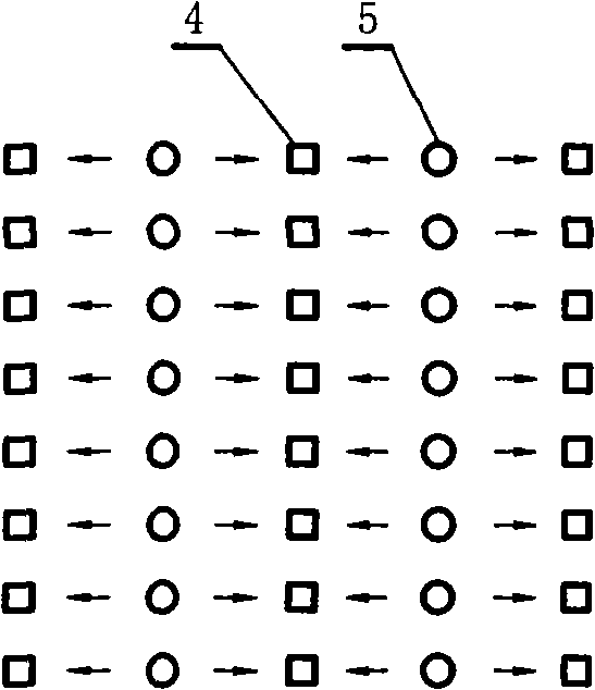
[0035] Embodiment 1: as attached figure 1 As shown, a ventilated reactor using a three-dimensional distributed ventilation method, the basic process is: after the material enters the screw distributor 2 from the storage hopper 1, it enters the reactor 3 through three distribution ports 11 and its regulating baffles. Under the action of gravity, the materials are naturally piled on the partition type material bed 7 and piled up on the ventilation pipe group in the reactor. The discharge volume or discharge speed is controlled by the partition type unloader 9 and collected by the drop hopper 8. The material that completes the reaction. A distributed air supply system is adopted, and the air is passed from the main air intake pipeline 6 to the terminal air supply pipeline group 5. Ventilation holes are distributed on the pipe wall (the pipe wall can also be grid-shaped) and the top is sealed, and the air passes through. Vent holes go into the material. Ventilation holes are als...

Embodiment 2

[0040] Embodiment 2: as attached Figure 8 As shown, similar to Example 1, a three-dimensional distributed ventilation method for biomass aerobic fermentation. The flow of materials is from top to bottom, basically the same as in Example 1. The air flow enters the material through the intake pipeline 23 and is sucked into the middle pipeline 22, and the air flow in the middle pipeline is sucked by the exhaust pipeline 21 and enters the exhaust system through the upper material layer. In this way, because the temperature of the lower layer material is higher after fermentation, the passing airflow enters the upper layer material through the intermediate pipeline, which can preheat the initial material. Due to the long natural heating cycle of organic matter fermentation, such a ventilation method is conducive to accelerating the heating of the upper material, allowing the rapid reproduction of biological bacteria, shortening the overall fermentation cycle, reducing the volume ...

Embodiment 3

[0044] Embodiment 3: Adopting is similar to attached Figure 8 The three-dimensional distributed ventilation system with the structure shown is used for pyrolysis of biomass or organic matter. The difference from fermentation is that the inside of the pyrolysis reactor must be sealed. The intake system is generally air, water vapor or oxygen, and the exhaust system is exhausted. Pyrolysis products are generally CO, H2, N2 and CH4. The basic process of operation is to start anaerobic heating to the temperature at which the pyrolysis reaction starts, gradually stop heating, start to let in air to oxidize organic matter to generate heat and heat up, and control the air intake to an appropriate temperature. Before the pyrolysis material enters the system, the air in it should be squeezed out. In order to avoid the coking and agglomeration of the pyrolysis product or control the falling speed, ribs or other protrusions can be set on the ventilation pipe network, or the ventilation ...


PUM


Abstract

The present invention provides a tridimensional distributed materials throughflow method and ventilated synthetic energy-saving method, applied to physical or chemical reaction field of biomass fermentation, thermal decomposition, drying, fluid and materials thermal transmission transfer of mass beween fluid and materials. Fluid inlet duct and outlet duct having throughflow holes bestrewed are arranged in materials, fluid passes through the materials layer through the throughflow in short distance to implement low resistance ventilation of materials, and uncontrolled ventilation without draught fan is implemented. Wind column can be added to use rotation stream inside the column and an optothermal increase system ventilation ability, and superabundance dynamic force can be used for power generation, and circumferential wind of the wind column can be used for power generation. the invention comprises methods of using warm air produced by discharged turbine tail steam condensation heat of thermal power generating plant to generate power or to be as uncontrolled ventilation smoke discharging dynamic force for boiler, and methods of uncontrolled ventilation fermentation type ecological urinal and polyporous material tridimensional arrangement throughflow thermal transmission transfer of mass employing polyporous material such as foam copper or the like.

Description

technical field [0001] The invention relates to a three-dimensional distributed material flow method and a ventilation comprehensive energy-saving method, which are applied to the fields of biomass aerobic fermentation, organic matter pyrolysis, material ventilation and drying, air purification, insect biological breeding, heat and mass transfer of fluids and materials, etc. The three-dimensional distributed flow treatment process, as well as the comprehensive energy saving including the use of chimney effect by the ventilation system to generate natural ventilation power by wind and light and heat. It also includes thermal power plants using the hot air generated by the condensation heat of steam turbine tail steam to generate electricity or become the power for boilers to exhaust smoke without induced draft fans, including natural ventilation fermented non-flushing ecological urinals, including porous materials such as foam copper for heat and mass transfer applications Wait...

Claims


Application Information

Patent Timeline
Patent Type & Authority Applications(China)
IPC IPC(8): F24F7/00C05F7/00C05F17/02C02F11/02A01F25/22F02G5/02
CPCY02T10/166Y02A40/20Y02P20/10Y02P20/133Y02P60/12Y02T10/12Y02W10/20Y02W10/33Y02W10/37
Inventor 张玉良
Owner 张玉良
Learn More