
Low-power consumption assembly line a/d converter by sharing operation amplifier

A technology of analog-to-digital converters and operational amplifiers, applied in the direction of analog-to-digital converters, differential amplifiers, DC-coupled DC amplifiers, etc., can solve the problem of high power consumption

Inactive Publication Date: 2008-10-01
FUDAN UNIV
View PDF0 Cites 39 Cited by
  • Summary
  • Abstract
  • Description
  • Claims
  • Application Information

AI Technical Summary

Problems solved by technology

[0005] The purpose of the present invention is to provide a low-power high-speed pipeline analog-to-digital converter shared by operational amplifiers, so as to overcome the problem of large power consumption of existing high-speed analog-to-digital converters

Method used


Image

  • Low-power consumption assembly line a/d converter by sharing operation amplifier
  • Low-power consumption assembly line a/d converter by sharing operation amplifier
  • Low-power consumption assembly line a/d converter by sharing operation amplifier

Examples


Embodiment Construction

[0018] Further describe the present invention below in conjunction with accompanying drawing.

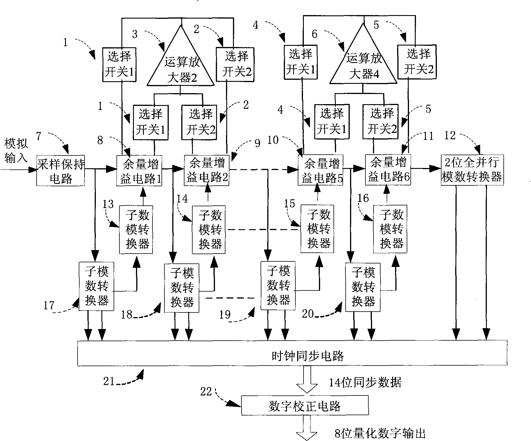
[0019] Analog-to-digital converter 71 is composed of input sample-and-hold circuit 7, switches 1-2, 4-5 for sharing operational amplifiers 3, 6, 6-stage margin gain circuits 8-11, and 1-stage two-bit full-parallel analog-to-digital conversion device 12, sub-ADCs 17-20, sub-DACs 13-16, pipeline output synchronous circuit 21 and digital correction circuit 22. The circuit block diagram is as follows image 3 shown. The sample-and-hold circuit 7 located at the input end samples the input signal through the gate voltage bootstrap switch, and uses an operational amplifier with a closed-loop gain of 1 to perform signal hold, and its output is quantized by the sub-analog-to-digital converter 14 to generate a two-digit digital output; at the same time, the margin gain circuit 8 also samples this output, amplifies the sampled voltage twice and subtracts it from the conversion result of the s...


PUM


Abstract

The present invention belongs to a technical field of an integrated circuit, and particularly to a low power consumption production line analog-digital converter which adopts an operational amplifier sharing. The analog-digital converter is composed of an input sampling holding circuit, a six-stage allowance gain circuit, an one-stage double-digit all-parallel analog-digital converter, a converting switch which is used for operational amplifier sharing, six sub-analog-digital converters, six sub-digital-analog converters, a production line output clock synchronous circuit and a digital correcting circuit. The sampling holding circuit and the six-stage allowance gain circuit are connected in sequence. The last stage is a double-digit all-parallel analog-digital converter. The input end of each stage of allowance gain circuit is connected with each stage of sub-analog-digital converter. Two continuous stages shares one operational amplifier. After the output clock synchronous circuit, the data with 14 digits is obtained, and after the digital correction of the digital correcting circuit, the final eight digit quantized output is obtained. The analog-digital converter realizes high speed and low power consumption.

Description

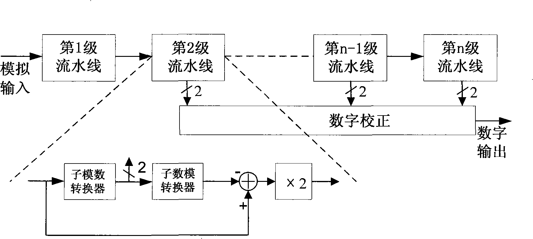
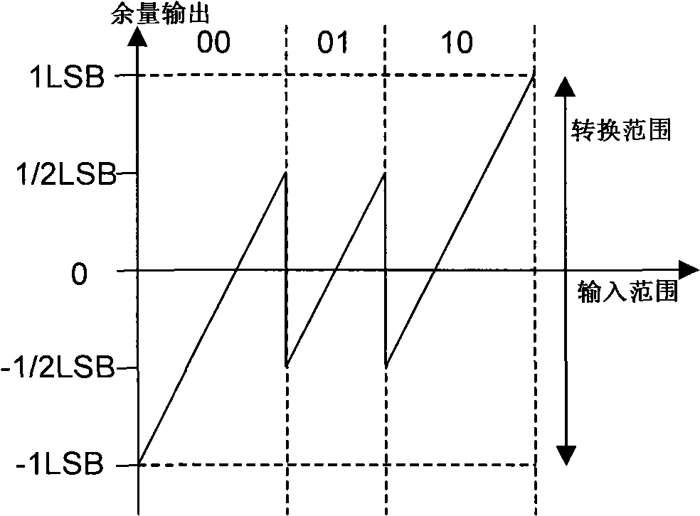
technical field [0001] The invention belongs to the technical field of integrated circuits, and in particular relates to a low-power pipeline analog-to-digital converter shared by an operational amplifier Background technique [0002] The design of high-speed, low-power analog-to-digital converters is the overall development trend in the design of mixed-signal system chips today, and it has a wide range of applications in data communication, liquid crystal display drivers, SOC systems, 10 / 100M Ethernet, etc. . Among the many kinds of analog-to-digital converter circuit structures, the pipeline structure has become the first choice because of its trade-off advantages in speed, accuracy and power consumption. [0003] The basic idea of ​​the pipeline structure is to evenly distribute the overall conversion accuracy requirements to each stage, and then combine the outputs of each stage to form the final conversion result. figure 1 It is a schematic diagram of the structure of...

Claims


Application Information

Patent Timeline
IPC IPC(8): H03M1/12G11C27/02H03K17/687H03F3/45
Inventor 任俊彦范明俊许俊李联
Owner FUDAN UNIV
Learn More