Roof
A roof surface and surface technology, applied in the direction of roof, roof covering, building, etc., can solve the problems of indoor influence, high temperature, unreasonable structure, etc., and achieve the effect of suppressing floating
- Summary
- Abstract
- Description
- Claims
- Application Information
AI Technical Summary
Problems solved by technology
Method used
Image

Examples
Embodiment 1
[0053] Embodiments of the present invention will be described based on the drawings.
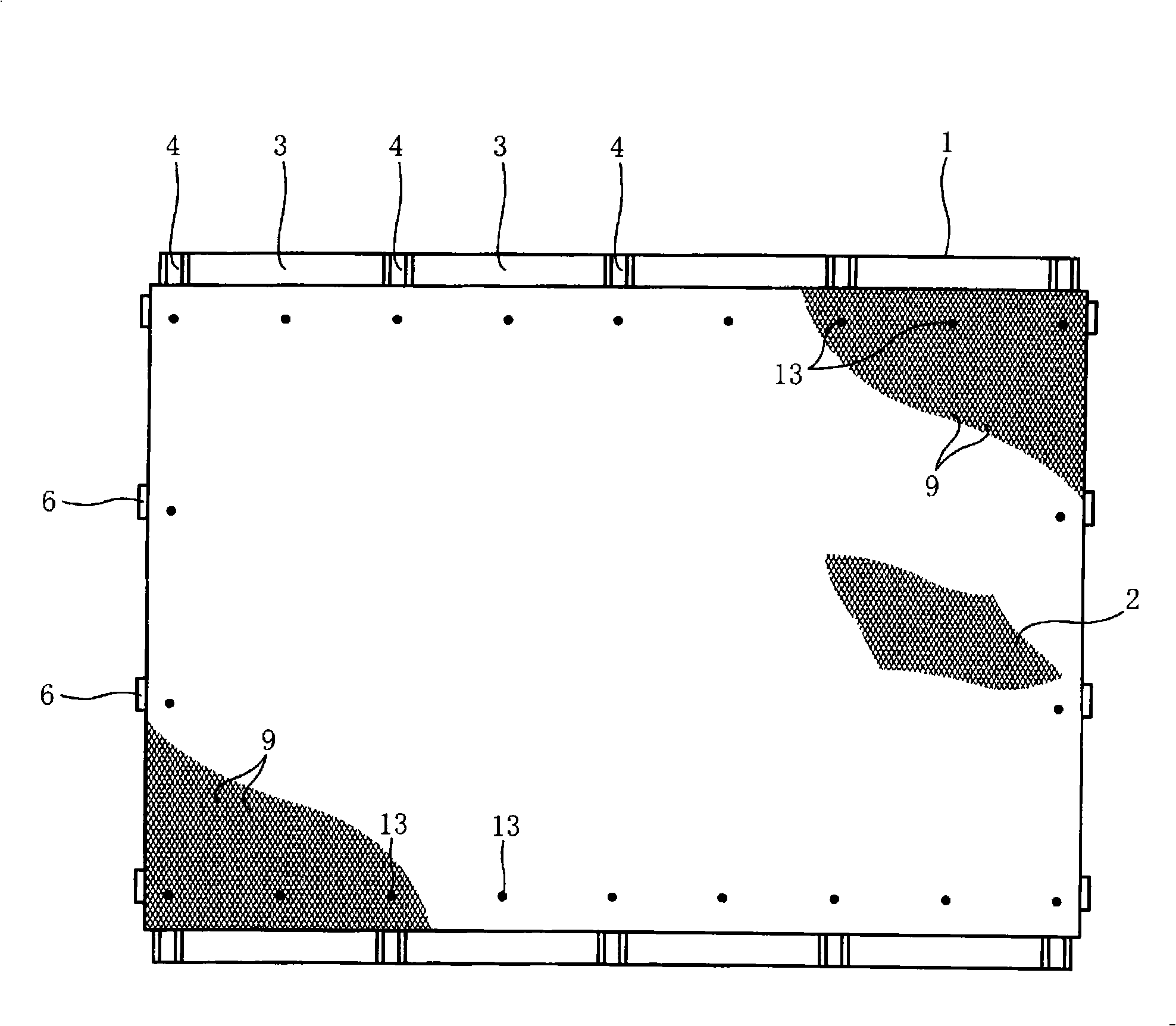
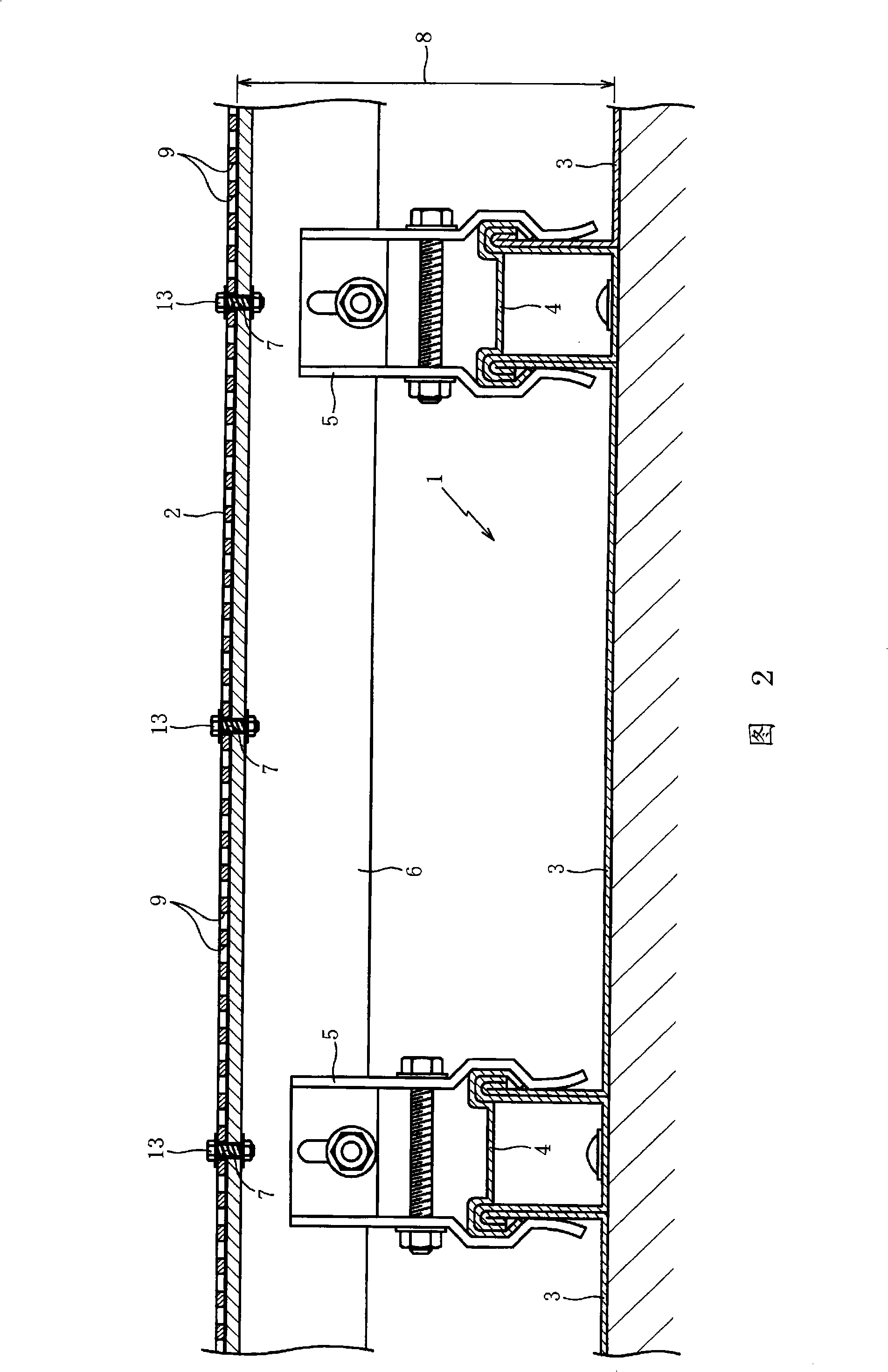
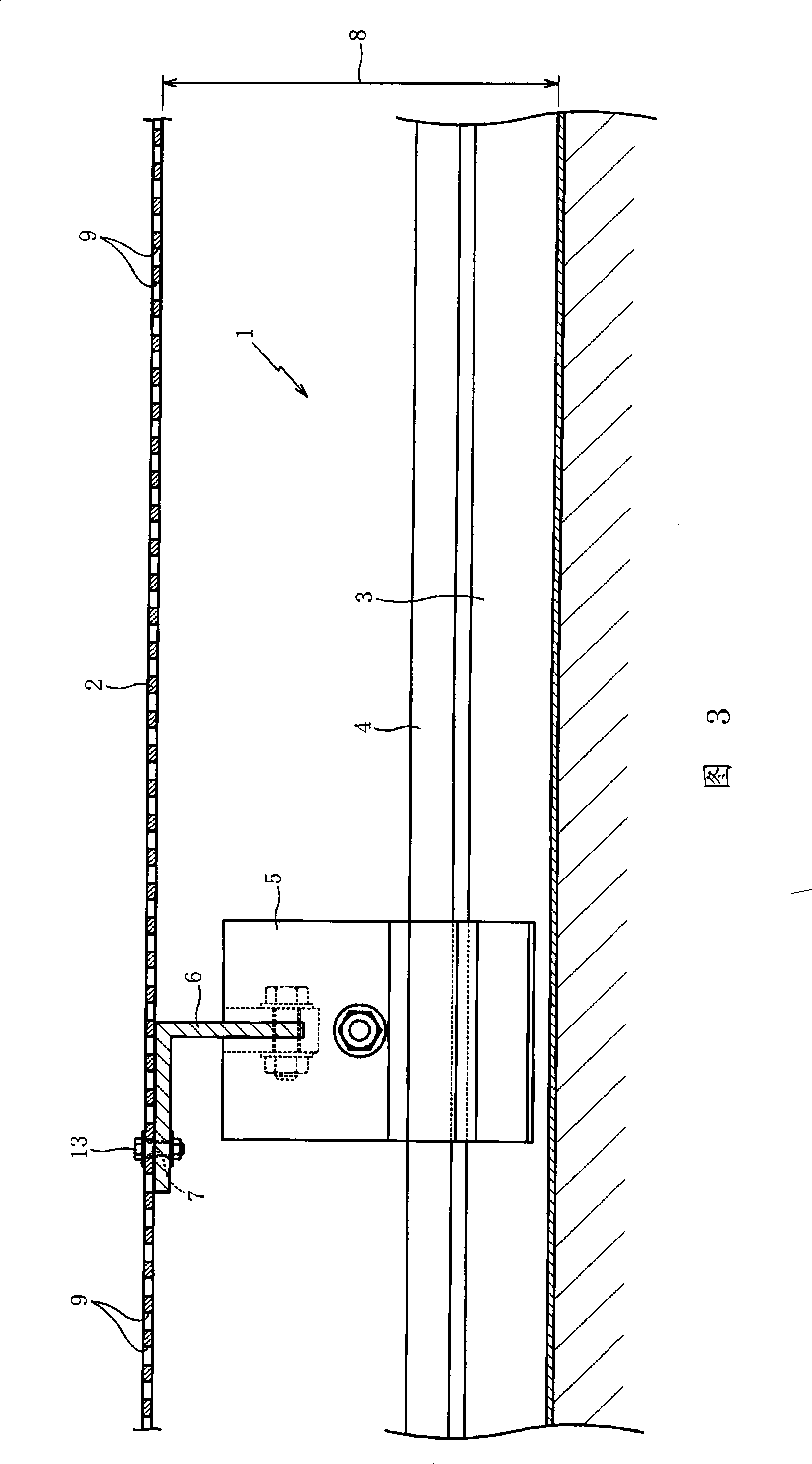
[0054] figure 1 It is a plan view showing a roof according to an embodiment of the present invention, and FIGS. 2 and 3 are cross-sectional views of main parts. This embodiment adopts a structure in which a planar base material 2 is laid on a roof 1 .
[0055] The roof 1 in the figure is the roof of the low-profile standing seam metal roofing method of the flat roof, and the angle iron 6 of the snow-proof parts 5 installed on the cover 4 of the joint of the roof panel 3 and the planar base material 2 are used. Mounting holes 7, bolts and nuts 13 are used to detachably install the planar base material 2, so that the planar base material 2 floats from the surface of the roof 1, and the planar base material 2 is laid on the roof 1 with a gap 8 provided.
[0056] The planar base material 2 is a thin plate or sheet, made of wood, resin, metal or cloth, etc., and is formed with a gap 9 that penet...
Embodiment 2
[0067] Figure 4 It is a top view showing a roof according to another embodiment of the present invention. FIGS. 5 and 6 are cross-sectional views of main parts. This embodiment has a structure in which a roof 1 is laid with a planar base material 2 .
[0068] The roof 1 is a flat roof, formed with folded plates 10, and slopes gently in the direction from top to bottom in the figure, and the concave lines (valleys) 11 and convex lines (peaks) 12 of the folded plates 10 are also arranged along the slope. It is formed in the up-down direction on the figure.
[0069] The roof 1 only needs to be formed in a concavo-convex shape, and the method and structure for forming the concavo-convex shape are not limited to folded plates and the like, and the type of the roof is also not limited.
[0070] The planar base material 2 is detachably fixed and paved by bolts and nuts 13 which are provided at the end of the first peripheral edge of the roof corresponding to the mounting holes 7 , ...
Embodiment 3
[0074] Figure 7 It is a plan view showing another embodiment. In this embodiment, a plurality of planar substrates 2, 2... are laid on the surface of a planar roof 1. Intervals 15 are provided between each planar substrate. It is possible to flow in and out from the portion provided with the gap 15 to the air duct 14 .
PUM
 Abstract
Description
Claims
Application Information
 - Generate Ideas
- Intellectual Property
- Life Sciences
- Materials
- Tech Scout
- Unparalleled Data Quality
- Higher Quality Content
- 60% Fewer Hallucinations
Browse by: Latest US Patents, China's latest patents, Technical Efficacy Thesaurus, Application Domain, Technology Topic, Popular Technical Reports.
© 2025 PatSnap. All rights reserved.Legal|Privacy policy|Modern Slavery Act Transparency Statement|Sitemap|About US| Contact US: help@patsnap.com