
Locomotive control loop grounding detection circuit and grounding detection method and wire break detection method

A grounding detection and control loop technology, applied in the direction of measuring electricity, measuring electrical variables, measuring resistance/reactance/impedance, etc., can solve problems such as failure to detect ground faults, failure of grounding protection methods, and inability of locomotive DC control systems to work. Achieve the effect of improving normal use efficiency and eliminating safety hazards

Inactive Publication Date: 2008-09-10
ZHUZHOU ELECTRIC LOCOMOTIVE CO
View PDF0 Cites 45 Cited by
  • Summary
  • Abstract
  • Description
  • Claims
  • Application Information

AI Technical Summary

Problems solved by technology

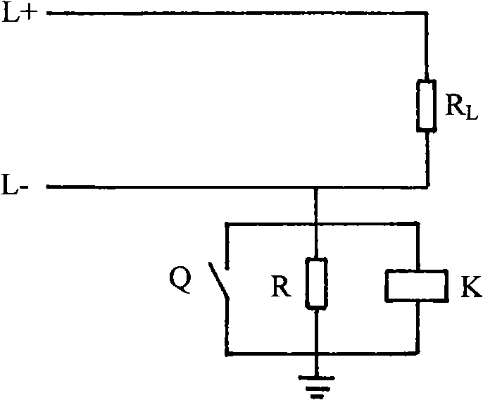
[0006] This method is simple and does not require too many components, but this method has obvious defects: if a point on the L- negative pole is also grounded, this grounding protection method will fail, and L+ and L- will be short-circuited directly, causing the locomotive The DC control system cannot work, and in severe cases, the electrical equipment on the control circuit may be burned
[0010] ① When the insulation resistance of the positive and negative poles decreases equally or the values ​​are close, even if the alarm limit has been exceeded, this method cannot detect the ground fault;
[0011] ②When the insulation resistance values ​​of the positive and negative poles to the ground are all within the normal range, but the difference is large, this method will generate false alarms

Method used


Image

  • Locomotive control loop grounding detection circuit and grounding detection method and wire break detection method
  • Locomotive control loop grounding detection circuit and grounding detection method and wire break detection method
  • Locomotive control loop grounding detection circuit and grounding detection method and wire break detection method

Examples


Embodiment Construction

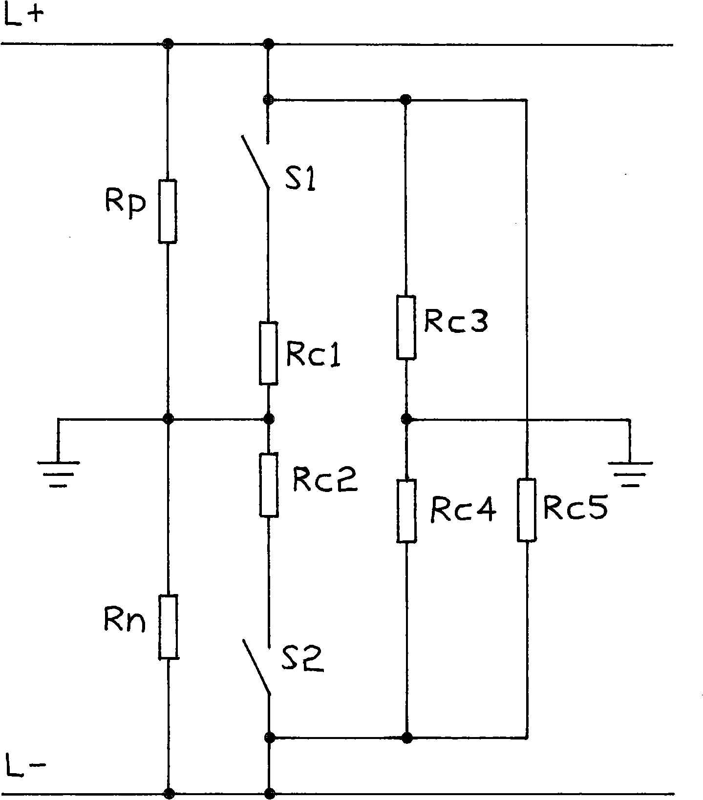
[0022] refer to figure 2 , L+ and L- are the positive and negative buses of the locomotive control loop, RP and RN are the insulation resistance of the positive and negative busbars to be tested to the ground respectively, RC1, RC2, RC3 and RC4 are precision resistors with known resistance values ​​for measurement, RC5 is the load, and S1 and S2 are switches .

[0023] Let the grid voltage of the control loop be U, RP / / RC3 be Rcp, RN / / RC4 be Rcn (" / / " means that two resistors are connected in parallel), and the voltages of Rcp and Rcn to ground are Ucp and Ucn respectively. The sizes of Ucp and Ucn can be obtained by collecting the voltages at both ends of Rc3 and Rc4 respectively.

[0024] When the switches S1 and S2 are all turned off, the measured voltages at both ends of RC3 and RC4 are Ucp0 and Ucn0. It can be seen from the figure that the measured Ucp0 and Ucn0 are the voltages between the positive and negative busbars and the ground at this time, and thus :

[002...


PUM


Abstract

The invention discloses a locomotive car duct pilot earth detecting circuit, which comprises a positive bus-bar, a negative bus-bar, a load resistance, line-to-ground isolated resistances of the positive bus-bar and the negative bus-bar, wherein, two detecting branch circuits are connected between the positive or the negative bus-bar and the earth respectively, one of which is composed of a known resistance and the other one is composed of the known resistance and a switch board in series connection. At the same time, an earth detecting method and a thread break error detecting method are further provided to be used for the locomotive car duct pilot earth detecting circuit. The locomotive car duct pilot earth detecting circuit can not only judges the earth errors existing in the locomotive car duct pilot by detecting the size of the line-to-ground isolated resistance of the positive and the negative bus-bar, but also detects the errors of thread breaking, which overcomes the shortcomings of traditional methods, alarms the earth errors in advance, eliminates the hidden safety trouble caused by the earth errors to regular running of locomotive cars and improves the normal using efficiency of locomotive cars.

Description

technical field [0001] The invention relates to grounding detection and disconnection detection of locomotive control loops. Background technique [0002] The locomotive 110V DC power supply is the working power supply for the locomotive control unit, signal communication system, relay protection circuit and other automatic devices. Due to the harsh operating environment of the locomotive, the insulation damage of 110V electrical equipment or wires often causes a ground fault in the circuit. Although a single-point ground fault will not affect the operation of the locomotive, if two or more multi-point ground faults occur In this case, the circuit may produce a short circuit and burn out the equipment and wires, thereby seriously affecting the safety and reliability of the normal operation of the locomotive. Therefore, it is very important to study the monitoring method of locomotive DC insulation. [0003] At present, there are two main control circuit grounding protectio...

Claims


Application Information

Patent Timeline
IPC IPC(8): G01R31/02G01R31/08G01R27/08B60L3/00
Inventor 陈爱军毛业军
Owner ZHUZHOU ELECTRIC LOCOMOTIVE CO
Learn More