Eureka AIR delivers breakthrough ideas for toughest innovation challenges, trusted by R&D personnel around the world.

Device for detecting vacuum ultraviolet spectrum

A technology of vacuum ultraviolet light and detection device, which is applied in the use of diffractive elements to generate spectrum, spectrum investigation, spectrum generation, etc., can solve the problem that the time response of fusion plasma cannot be satisfied, the spatial density of the detector unit cannot be very high, and it is distributed in the Roland circle. The above problems are not easily disturbed, the operating environment requirements are low, and the time response is good.

Active Publication Date: 2008-09-03
TSINGHUA UNIV
View PDF0 Cites 12 Cited by
  • Summary
  • Abstract
  • Description
  • Claims
  • Application Information

AI Technical Summary

Problems solved by technology

However, despite the advantages of high efficiency, the traditional grazing incidence spectrometer has some problems in cooperating with the flat panel detector: in fact, after the incident light is split and focused by the grating, its focal point is not on the same plane, but is distributed on the Rowland disk
However, as far as the ring grating detection system currently in use is concerned: its focal length is relatively short (typically no more than 250mm, while the grazing incidence system can reach more than 2000mm), which leads to lower resolution; its imaging area is also small , the spatial density of the detector unit cannot be very high, which in turn leads to lower pixel resolution; in addition, the wavelength range covered by each ring grating is also small, so that it takes about 4 ring gratings to cover the wavelength range of 1-200nm grating (grazing incidence system can use only one grating)
[0006] In addition, there is another way to move the detector along the Rowland circle to scan light of different wavelengths, such as the vacuum ultraviolet spectrometer used to study some low-temperature plasmas with long-term stable discharges, but this cannot meet the requirements of the fusion plasma research. Basic Time Response Requirements

Method used


Image

  • Device for detecting vacuum ultraviolet spectrum

Examples


Embodiment Construction

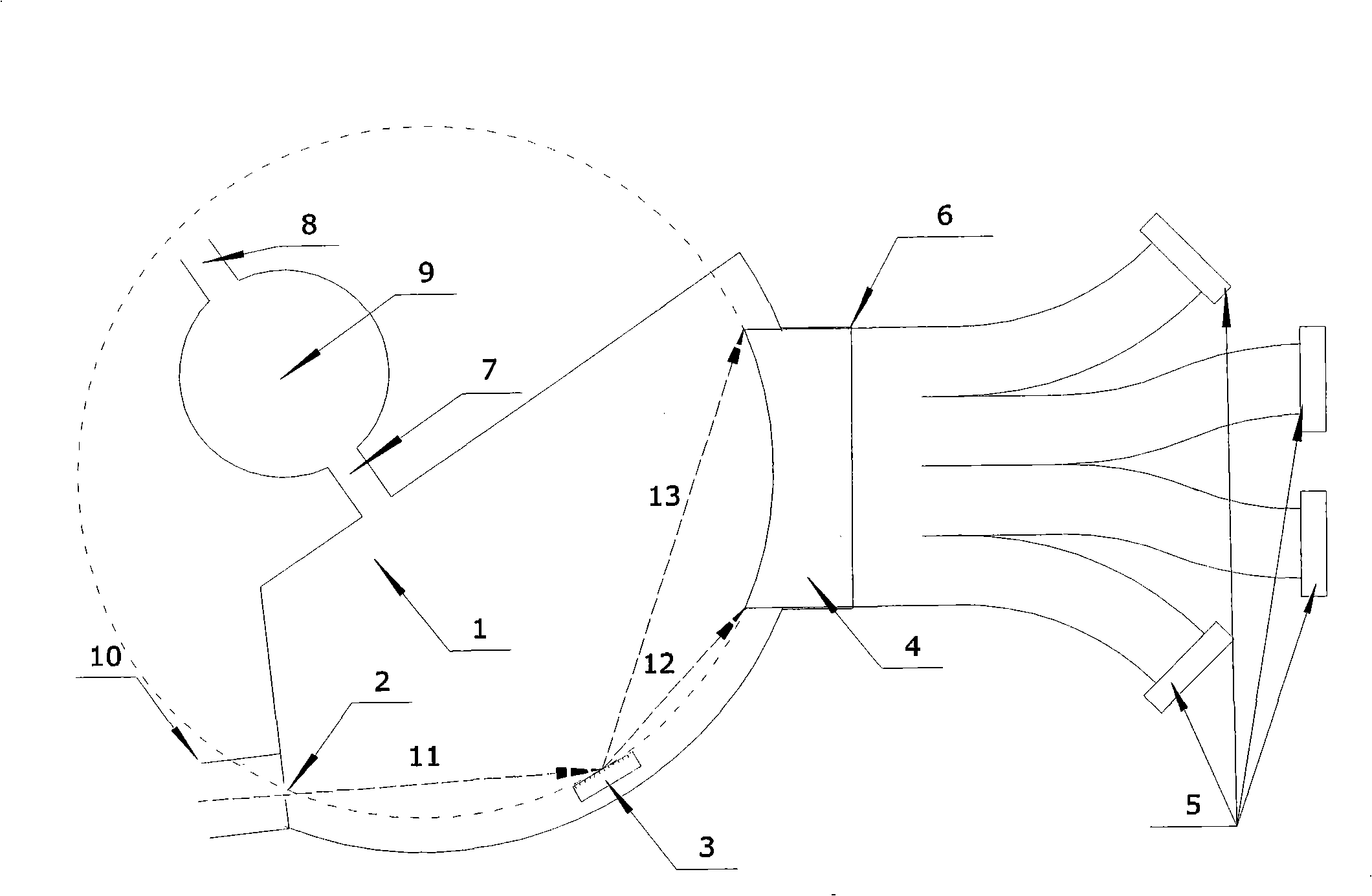
[0015] mistake! Reference source not found. Specific embodiments of the invention are given schematically. The incident slit 2, the concave grating 3, the optical fiber array 4 and a plurality of flat panel detectors 5 constitute the optical system of the vacuum ultraviolet spectrum detection device. The entrance slit 2 is parallel to the generatrices of the grating 3 . The grating 3 is a grazing incidence grating covering a wavelength range of 1-200nm and a focal length of 1000-2000mm. One end face of the fiber array 4 coincides with the Rowland circular surface determined by the incident slit 2 and the concave grating 3, covering the focal distribution of the vacuum ultraviolet light incident through the slit within a certain wavelength range. The end face is also coated with a fluorescent substance that converts vacuum ultraviolet light into visible light. The other end of the fiber array 4 is bifurcated into several sub-fiber arrays. The end faces of these sub-fiber ar...


PUM


Abstract

The invention provides a vacuum ultraviolet spectroscopy detecting device, which belongs to the field of spectrum analysis. The device includes: an entrance slit (2), a concave grating (3), a optical fiber array (4) and a flat plate detector (5). The entrance slit (2) and concave grating (3) are fixed in the vacuum cavity (1), one head face of the optical fiber array (4) coincides with the Rowland circle determined by the entrance slit (2) and the concave grating (3). The head face of the optical fiber array (4) is painted with fluorescent substance which can transform vacuum ultraviolet light into visible light, the other end face bifurcates into a number of sub-optical fiber arrays, and the end face of the sub-optical fiber array is a plain face and is connected with one flat plate detector (5). The device can measure vacuum ultraviolet spectroscopy within a certain range of wavelength simultaneously, and achieve the optical spectrum and pixel resolution of glancing incidence grating vacuum ultraviolet spectrometer, the testing time responses well and the device has high sensitivity; the moveable component is not needed in the vacuum cavity, and the structure is simple and reliable.

Description

technical field [0001] The invention relates to a detection device for vacuum ultraviolet (VUV) radiation and VUV band atomic emission spectrum, which belongs to the detection instrument in the field of spectrum analysis. Background technique [0002] To understand the behavior of impurity components in fusion plasma, the most basic method is to study them through the characteristic lines of various nuclides in the emission spectrum. For a typical magnetic confinement nuclear fusion experimental device, the plasma discharge conditions are roughly 1019-1020m-3 electron density and 0.1-10keV electron temperature. At this time, most of the spectral lines emitted by impurity nuclides (ions) are vacuum ultraviolet light in the wavelength range of 1-200nm. Therefore, detection of emission spectra in this range is the main means for us to diagnose impurities under the premise of ensuring the following conditions: First, the simultaneous detection of spectra must be ensured, that i...

Claims


Application Information

Patent Timeline
IPC IPC(8): G01N21/67G01J3/20G01J3/36
Inventor 谭熠蒲以康
Owner TSINGHUA UNIV
Why Eureka
Eureka Blog
Learn More