
Piezoelectric ceramic electro-acoustic conversion device

A technology of electro-acoustic transducers and piezoelectric ceramics, which is applied in the direction of piezoelectric/electrostrictive transducers, sensors, electrical components, etc., and can solve problems such as poor piezoelectric performance, difficulty in thinning, and non-compliance with thinning.

Inactive Publication Date: 2008-08-20
JIANGSU YUCHENG ELECTRONICS
View PDF3 Cites 1 Cited by
  • Summary
  • Abstract
  • Description
  • Claims
  • Application Information

AI Technical Summary

Problems solved by technology

This electro-acoustic converter has high-frequency characteristics, narrow frequency band, large cavity and volume, and has the disadvantage of being unable to produce sound in the low-frequency range. Usually, the thickness is more than 2mm and the weight is greater than 2g. Product Thinning Requirements
[0003] Chinese invention patent 200510077322.7 discloses a "piezoelectric speaker", which consists of two conductive metal foils on the two main surfaces to form a conductive path, which will cause the resonant frequency to drift, the piezoelectric performance is poor, and the volume is large
[0004] Chinese invention patent 02154318.6 discloses a piezoelectric speaker. The diaphragm of the piezoelectric ceramic is not a multilayer piezoelectric ceramic. It has a narrow frequency band, a complex structure, and a large volume, which is difficult to meet the requirements of thinning.
[0005] Chinese utility model patent 200520025618.x discloses a "piezoelectric speaker", which belongs to a single-chip piezoelectric speaker, and its volume is large, so it is difficult to meet the requirements of thinning

Method used


Image

  • Piezoelectric ceramic electro-acoustic conversion device
  • Piezoelectric ceramic electro-acoustic conversion device

Examples


Embodiment Construction

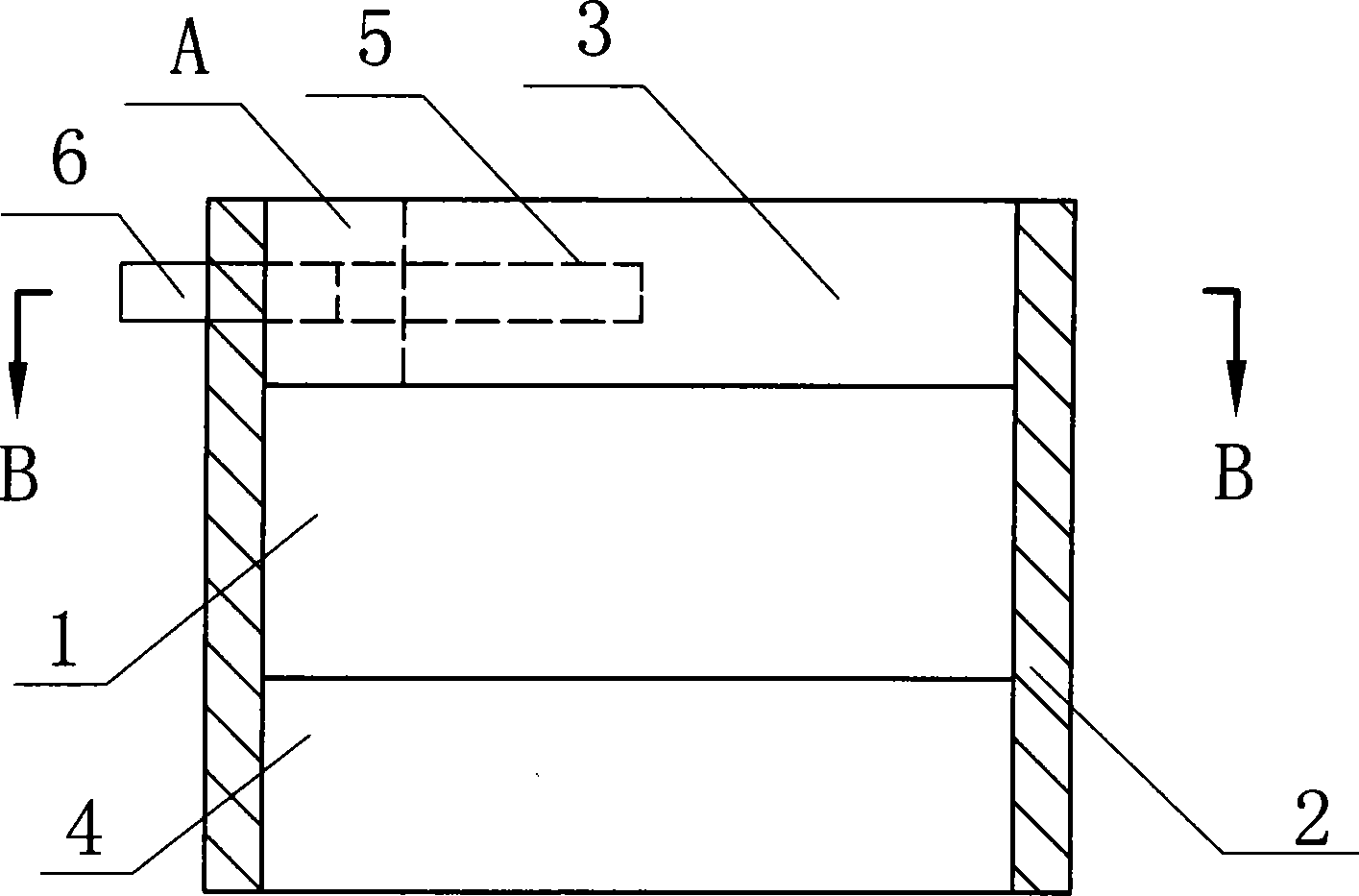
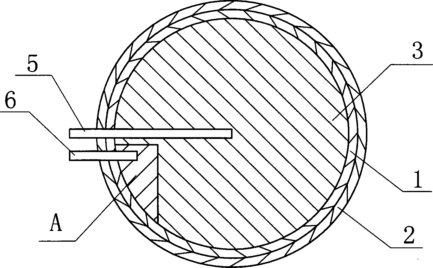
[0016] see figure 1 , a piezoelectric ceramic electroacoustic transducer, including a vibrating plate 1, a frame 2, a conductive path with electrodes 5, 6, and its innovative point is: it also includes a composite vibrating plate 1, piezoelectric ceramic membranes 3, 4 Diaphragm, the composite diaphragm is fixedly connected to the frame 2, the main surface of the vibration plate 1 is bonded with the piezoelectric ceramic film 3 to form one side of the composite diaphragm, and the other side of the vibration plate 1 is bonded with the pressure The electric ceramic film 4 constitutes the other side of the composite diaphragm, and the two electrodes 5 and 6 of the conductive path are respectively fixed on the same face of the composite diaphragm, that is, respectively fixed on the piezoelectric ceramic film 3 .

[0017] Depend on figure 1 and figure 2 It is shown that an area A is arranged on the piezoelectric ceramic film 3, and the electrode 6 is connected to the area A on t...


PUM

PropertyMeasurementUnit
Diameteraaaaaaaaaa

Abstract

The invention provides a piezoelectric ceramics electron-phonon converter which comprises a vibrating board, a frame, a conductive path, also comprises a composite diaphragm composed of the vibrating board and a piezoelectric ceramics film, the vibrating board main-surface is bonded with first piezoelectric ceramics film, another surface is bonded with second piezoelectric ceramics film, two electrodes are fixed on same surface of the composite diaphragm respectively, namely first piezoelectric ceramics film; A region is set on first piezoelectric ceramics film, one electrode links with the A region which is non-conducting with other part of first piezoelectric ceramics film and is conducting with second piezoelectric ceramics film, another electrode is conducting with other part of first piezoelectric ceramics film except for A region. The minitype piezoelectric ceramics electron-phonon converter without cavity is ultra-thin and has less than 1mm thickness, about 1g weight, resonant frequency 1KHZ, wide frequency response range, clear and nature tone quality. The piezoelectric ceramics electron-phonon converter is suitable for mobile phone, wireless telephone, notebook computer, digital camera, blue-tooth earphone, MP3, MP4, PDA etc.

Description

technical field [0001] The invention relates to a piezoelectric ceramic electroacoustic transducer, in particular to a miniature cavity-free piezoelectric ceramic broadband electroacoustic transducer. Background technique [0002] Piezoelectric ceramic electroacoustic converter is a new type of electronic device combined with electroacoustics, and it is also a key component of communication in modern production and life. It can be applied to mobile phones, cordless phones, notebook computers, digital cameras, Bluetooth headsets, MP3, MP4 , PDA and other digital products. The vibrating membrane of the commonly used piezoelectric ceramic electroacoustic transducer is composed of a single-layer and double-layer piezoelectric ceramic membrane and a metal flat diaphragm, but it needs a cavity of a certain size to produce sound, which belongs to the high-frequency electroacoustic transducer . This electro-acoustic converter has high-frequency characteristics, narrow frequency ba...

Claims


Application Information

Patent Timeline
IPC IPC(8): H04R17/00
Inventor 徐国荣程锬顺黄新友王韶华
Owner JIANGSU YUCHENG ELECTRONICS
Learn More