
Fan base and manufacturing method thereof

A manufacturing method and fan technology, applied to parts of pumping devices for elastic fluid, non-variable pumps, machines/engines, etc., can solve the problem of thinning the bearing seat 200, the bottom plate 100 and the bearing The seat is 200 thick, and it is difficult to meet the requirements of thinning, etc., to achieve the effect of reducing production costs, meeting thinning, and high strength

Inactive Publication Date: 2017-03-15
FURUI PRECISE COMPONENT (KUNSHAN) CO LTD +1
View PDF8 Cites 0 Cited by
  • Summary
  • Abstract
  • Description
  • Claims
  • Application Information

AI Technical Summary

Problems solved by technology

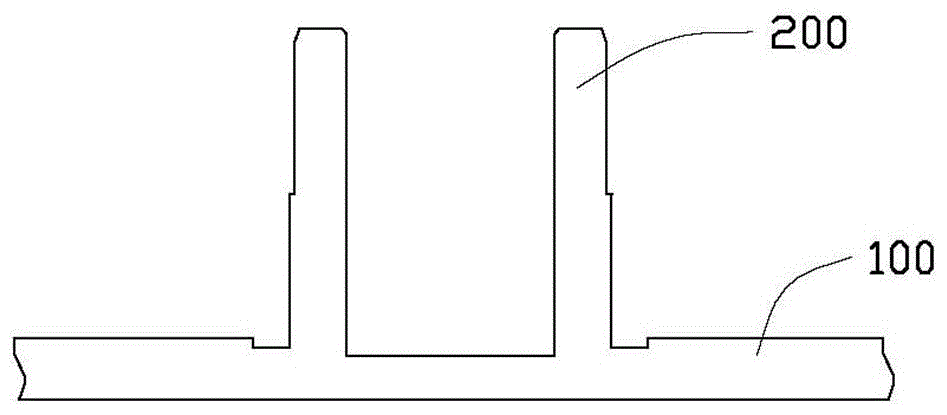
see figure 1 , in the prior art, the bottom plate 100 and the bearing seat 200 are generally integrally formed by plastic, but the integrally formed structure of plastic is used. Due to the limitation of the thickness of the plastic, the formed bottom plate 100 and the bearing seat 200 are thicker, which is difficult to Meet the requirements of thinning
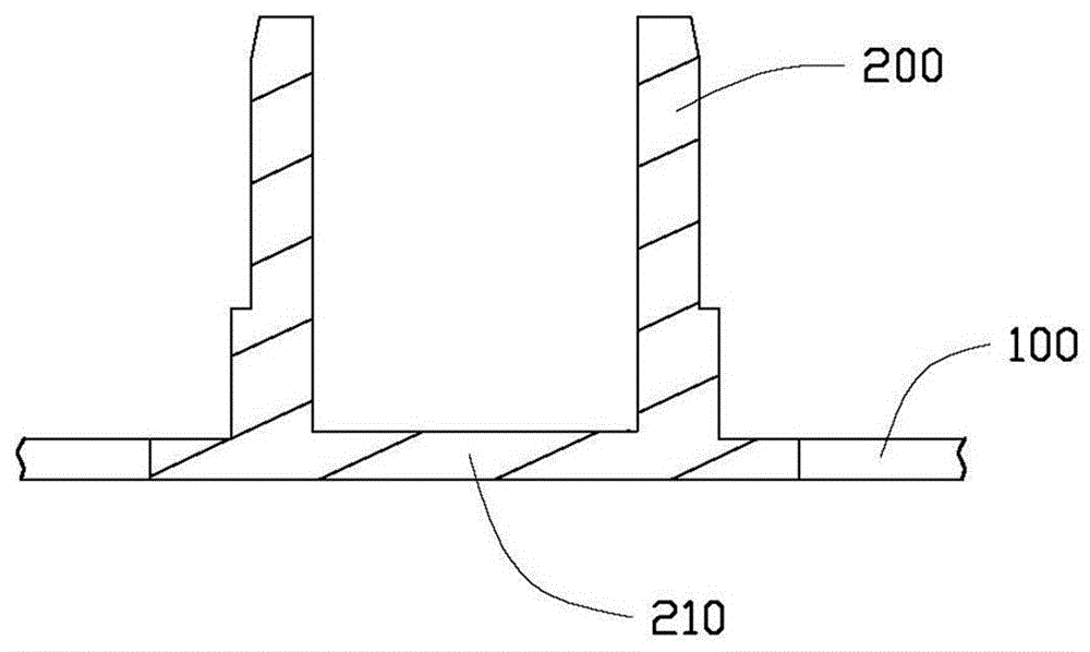
see figure 2 , in the prior art, there is also a structure in which the bottom plate 100 of metal material is combined with the bearing seat 200 of plastic material. This structure is that the bearing seat 200 of plastic material is injection molded on the bottom plate 100 of metal material, but The bottom wall 210 of the bearing seat 200 of the material also has restrictions on the thickness of the molding, and it is difficult to meet the requirements of thinning the bearing seat 200
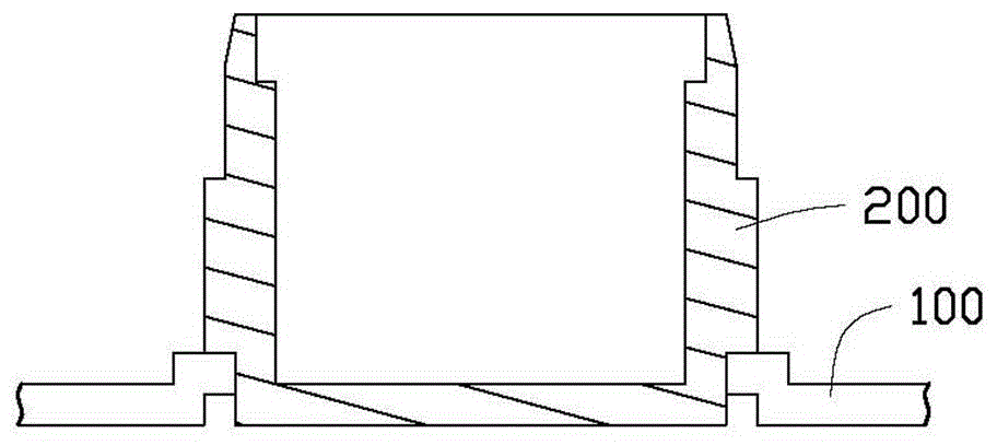
see image 3 , in the prior art, there is also a structure of riveting the bottom plate 100 of metal material and the bearing seat 200 of metal material, but this will increase a riveting process, thereby increasing the production cost of the fan seat

Method used


Image

  • Fan base and manufacturing method thereof
  • Fan base and manufacturing method thereof
  • Fan base and manufacturing method thereof

Examples


Embodiment Construction

[0018] The present invention will be further described in detail below in conjunction with the accompanying drawings.

[0019] see Figure 4 A fan base 10 provided by an embodiment of the present invention includes a metal bottom plate 11 and a plastic bearing post 12 formed on the metal bottom plate 11 .

[0020] see Figure 5 , Image 6 as well as Figure 7 , the metal bottom plate 11 is used to cooperate with a top plate (not shown in the figure) to jointly form a fan frame for accommodating fan blades. A roughly circular air inlet 111 is defined on the metal bottom plate 11 , a bearing plate 112 is formed in the center of the air inlet 111 , and the bearing plate 112 is connected to the edge of the air inlet 111 through three connecting plates 113 . The carrying plate 112 is also provided with a number of substantially crescent-shaped openings 114, the openings 114 are arranged around the center of the carrying plate 112, and the inner arc of the opening 114 faces the ...


PUM


Abstract

A fan base comprises a metal baseplate and a plastic bearing column formed on the metal baseplate. A plurality of bent pieces are formed on the metal baseplate, each bent piece is bent upwards from the metal baseplate, the plastic bearing column is formed on the metal baseplate by means of injection molding, the metal baseplate is attached to the bottom surface of the plastic bearing column, and the bent pieces are embedded in the plastic bearing column. Compared with a plastic bearing seat bottom wall, the bottom wall, composed of the metal baseplate, of the plastic bearing column is higher in strength, thinner and capable of meeting the requirement on thinning. The invention further provides a manufacturing method of the fan base.

Description

technical field [0001] The invention relates to a fan base and a manufacturing method thereof. Background technique [0002] A traditional fan seat includes a bottom plate and a bearing seat formed on the bottom plate, wherein the bearing seat includes a cylindrical side wall and a bottom wall. see figure 1 , in the prior art, the bottom plate 100 and the bearing seat 200 are generally integrally formed by plastic, but the integrally formed structure of plastic is used. Due to the limitation of the thickness of the plastic, the formed bottom plate 100 and the bearing seat 200 are thicker, which is difficult to Meet the requirements of thinning. see figure 2 , in the prior art, there is also a structure in which the bottom plate 100 of metal material is combined with the bearing seat 200 of plastic material. This structure is that the bearing seat 200 of plastic material is injection-molded on the bottom plate 100 of metal material, but The material of the bottom wall 21...

Claims


Application Information

Patent Timeline
Patent Type & Authority Patents(China)
IPC IPC(8): F04D29/00B29C45/14
Inventor 陈文正
Owner FURUI PRECISE COMPONENT (KUNSHAN) CO LTD
Learn More