
Thinned connector

A technology of connectors and connecting sections, which is applied in the direction of connection, parts of connecting devices, contact parts, etc., can solve problems such as limited use, inconvenience, and obstruction of flexible circuit boards, and achieve stable boards and reduced elasticity. The effect of dynamic space

Inactive Publication Date: 2012-02-08
EXCEL CELL ELECTRONICS
View PDF2 Cites 0 Cited by
  • Summary
  • Abstract
  • Description
  • Claims
  • Application Information

AI Technical Summary

Problems solved by technology

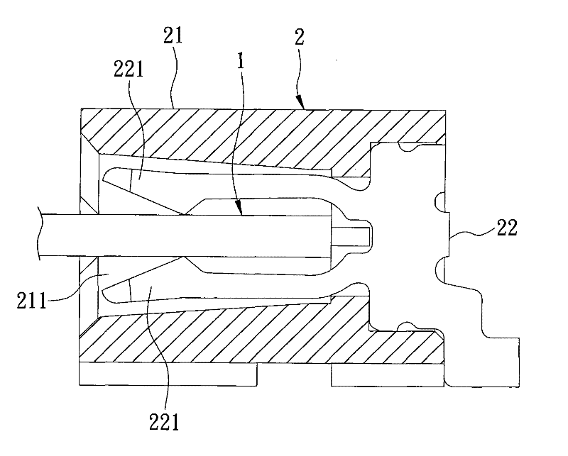
[0004] 1. Since the aforementioned elastic buckle 221 will spring relatively, therefore, the slot 211 of the casing 21 must have enough space, so that the aforementioned elastic buckle 221 can spring outward or move outward without hindrance. The inner side is clamped, and the design of expanding the slot 211 will keep the height of the housing 21 at least 2mm-3mm and cannot be reduced
[0005] 2. The clamping method of the aforementioned elastic buckle 221 with both arms will form a large obstacle to the inserted flexible circuit board 1, causing the user to apply a large external force to successfully complete the insertion. more laborious and inconvenient
[0006] 3. The flexible circuit board 1 is limited by the clamping method of the double-armed elastic buckle 221, and can only be inserted in the middle of the connector 2, so that it is impossible to change the position of the housing 21 during design. The position of slot 211 has the disadvantage of limited use

Method used


Image

  • Thinned connector
  • Thinned connector
  • Thinned connector

Examples


Embodiment Construction

[0024] The present invention will be described in detail below in conjunction with the accompanying drawings and embodiments. Before the present invention is described in detail, it is noted that in the following description, similar elements are denoted by the same numerals.

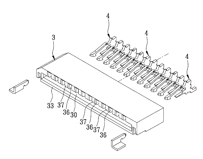
[0025] refer to image 3 , Figure 4 ,and Figure 5 , a first preferred embodiment of the thinned connector of the present invention includes a housing 3 and a plurality of terminals 4 .

[0026] The housing 3 has a first slot surface 31 defining a slot 30 (such as Figure 6 ) and a second groove surface 32 (such as Figure 6 ), exposing a first side 33 of the slot 30, communicating with the slot 30 along an axis X direction and revealing a second side 34 (such as Figure 6 ) of a card slot 35 (such as Figure 6 ), and a plurality of bumps 37 formed on the first groove surface 31 and partitioned with a plurality of compartments 36 .

[0027] The aforesaid terminals 4 go deep into the slot 30 from...


PUM


Abstract

The invention discloses a thinned connector, which comprises a shell and at least one terminal, wherein the shell has a first groove surface and a second groove surface on which an insertion groove is formed; the insertion groove is exposed on a first side face; the terminal is arranged in the shell and has a reverse hook and an inclined surface; the reverse hook springs in the insertion groove; the inclined surface is pressed against the second groove surface; and a distance between the inclined surface and the first groove surface is gradually reduced along the insertion direction of the insertion groove through the first side face. Therefore, by using the single-arm-type reverse hook, a required springing space is reduced, and requirements for thinning are met; and the reverse hook is matched with the inclined surface to force a plate piece to be gradually inserted into the insertion groove, so that the aim of stabilizing the plate piece can be fulfilled under the condition of reducing insertion resistance.

Description

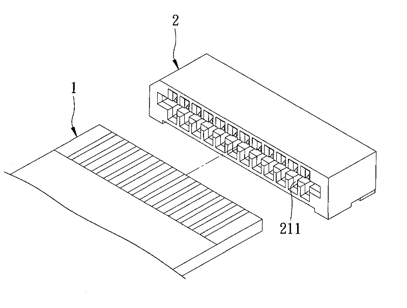
technical field [0001] The invention relates to a connector, in particular to a thinned connector for inserting a board. Background technique [0002] refer to figure 1 , figure 2 , taking a connector 2 generally used for inserting a flexible printed circuit board (FPC) 1 as an example, it mainly includes a housing 21 and a metal terminal 22 inserted in the housing 21 . The housing 21 has a slot 211 . The terminal 22 has two elastic buckles 221 relatively elastic in the slot 211 . Thereby, when the flexible printed circuit board 1 is inserted into the slot 211 of the casing 21, it will first push the aforementioned elastic buckle 221 to spring outward, and wait for the flexible printed circuit board 1 to be inserted into the slot. After 211, the aforementioned elastic buckle 221 utilizes its own elastic force to pinch the flexible circuit board 1 inward, so that the flexible circuit board 1 is positioned and electrically connected to the terminal 22 . [0003] However,...

Claims


Application Information

Patent Timeline
Patent Type & Authority Applications(China)
IPC IPC(8): H01R12/77H01R13/24H01R13/629
Inventor 林志明
Owner EXCEL CELL ELECTRONICS
Learn More