
Backlight module

A technology of a backlight module and a phosphor layer, applied in the field of light-emitting diode backlight modules, can solve the problems of unfavorable thin-shaped design of backlight modules, inconvenient heat dissipation, etc., and achieve the effect of reducing height and satisfying thinning

Active Publication Date: 2017-12-26
SHENZHEN ZHONGSHEN OPTOELECTRONICS
View PDF6 Cites 0 Cited by
  • Summary
  • Abstract
  • Description
  • Claims
  • Application Information

AI Technical Summary

Problems solved by technology

For the backlight module with this structure, because these light-emitting diode packaging structures directly protrude outward from the circuit board, the backlight module has a relatively large height in the vertical direction, which is not conducive to the thin design of the backlight module and inconvenient heat dissipation.

Method used


Image

  • Backlight module

Examples


Embodiment Construction

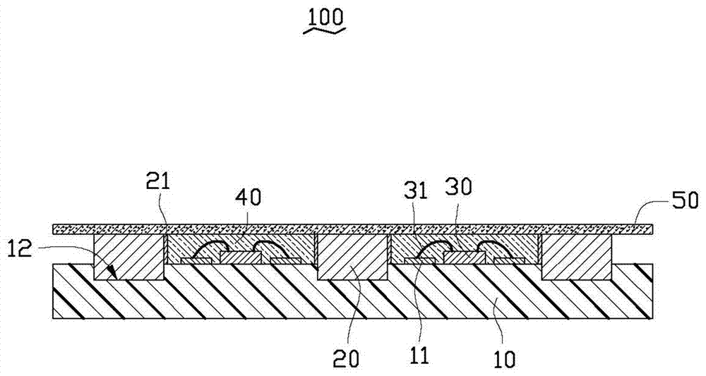
[0010] see figure 1 , the backlight module 100 of the present invention includes a circuit board 10, a plurality of hollow frames 20 fixed on the circuit board 10, light-emitting diode chips fixed on the circuit board 10 and housed in each frame 20 respectively 30. The colloid 40 filled in the frames 20 and wrapping the LED chip 30 and a phosphor layer 50 fixed on the top of the frames 20 .

[0011] The circuit board 10 is a long board with a flat top surface and a bottom surface parallel to the top surface. A circuit (not shown) and conductive contacts 11 electrically connected to the circuit are formed on the top surface. The conductive contacts 11 protrude from the top surface and are arranged at intervals. Each LED has two metal wires 31 . The LED chips 30 are mounted on the top surface of the circuit board 10 and the two metal wires 31 are electrically connected to the two conductive contacts 11 respectively. The height of the conductive contacts 11 protruding upward ...


PUM


Abstract

The invention discloses a backlight module. The backlight module comprises a circuit board, a light-emitting diode chip and a frame body enclosing the light-emitting diode chip, the light-emitting diode chip is attached to the top surface of the circuit board, the circuit board is depressed to form a holding groove, and the bottom end of the frame body is held in the holding groove to be fixed to the circuit board. In the backlight module, the light-emitting diode chip is directly attached to the top surface of the circuit board and the bottom end of the frame body enclosing the light-emitting diode is held in the holding groove, thereby reducing the vertical height of the back module in comparison to the conventional backlight module, and meeting the requirement of thinning.

Description

technical field [0001] The invention relates to a backlight module, in particular to a light emitting diode backlight module. Background technique [0002] A traditional backlight module includes a circuit board and a plurality of light-emitting diode packaging structures mounted at intervals on one side of the circuit board. Each light-emitting diode package structure includes two spaced electrodes arranged side by side, a light-emitting diode chip fixed on one electrode and electrically connected to the two electrodes, an inner wall fixed on the two electrodes and surrounding the light-emitting diode chip An empty frame body and a fluorescent powder layer accommodated in the frame body and wrapping the light-emitting diode chip. The ends of the two electrodes are welded on the conductive contacts of the circuit board through solder paste. The backlight module with this structure has a large height in the vertical direction because the LED packaging structures directly pr...

Claims


Application Information

Patent Timeline
Patent Type & Authority Patents(China)
IPC IPC(8): F21S8/00F21V19/00H01L33/48F21Y115/10
Inventor 陈楚耿
Owner SHENZHEN ZHONGSHEN OPTOELECTRONICS
Learn More