Adjusting method of close-packed optical fiber array imaging and laser imaging device thereof

A correction method and laser imaging technology, applied in photoelectric typesetting devices, phototypesetting devices, printing and other directions, can solve the problems of low integration, slow running speed, complicated delay mechanism structure, etc., and achieve high integration, easy implementation, simple structure

Active Publication Date: 2008-07-23
HANS LASER TECH IND GRP CO LTD
View PDF1 Cites 2 Cited by
  • Summary
  • Abstract
  • Description
  • Claims
  • Application Information

AI Technical Summary

Problems solved by technology

[0003] In order to solve technical problems such as complex structure, low integration, and slow running speed of the time delay mechanism used for optical fiber close-packed array correction in the prior art, the present invention proposes a field-programmable gate array (FPGA)-based optical fiber close-packed array Calibration method for array imaging and laser imaging device using the method
[0004] The technical solution adopted by the present invention to solve the technical problems of the delay mechanism used in the correction of the optical fiber close-packed array in the prior art is complex in structure, low in integration degree, and slow in operation speed. It is to provide a correction method for optical fiber close-packed array imaging, The optical fiber close-packed array includes multiple optical fibers arranged in a straight line and is inclined at a certain angle relative to the predetermined direction of the image plane. The correction method includes: a. receiving image signals corresponding to each optical fiber in the optical fiber close-packed array; b. The image signals are respectively delayed in the shift register of the FPGA; c. Utilize each delayed image signal to drive the laser light source corresponding to each optical fiber so that the synchronously received image signals are sequentially imaged at predetermined time intervals through the optical fiber close-packed array image plane

Method used


Image

  • Adjusting method of close-packed optical fiber array imaging and laser imaging device thereof
  • Adjusting method of close-packed optical fiber array imaging and laser imaging device thereof
  • Adjusting method of close-packed optical fiber array imaging and laser imaging device thereof

Examples


Embodiment Construction

[0019] Hereinafter, the present invention will be described in detail with reference to the accompanying drawings and taking a laser imagesetter with a 32-way optical fiber close-packed array as an example. However, it is obvious to those skilled in the art that the present invention is also applicable to other laser imaging devices using tilted optical close-packed arrays.

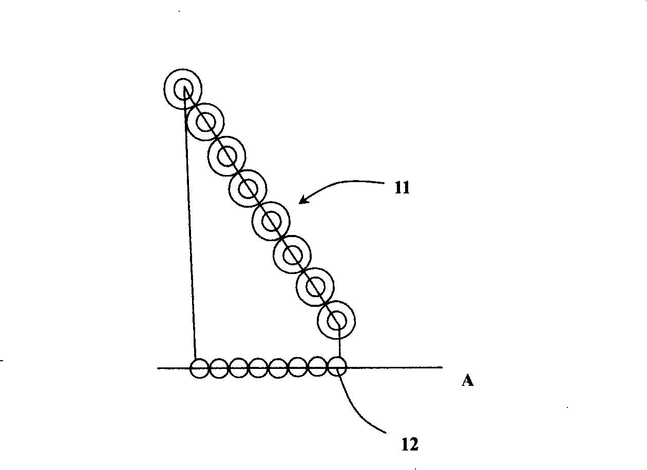
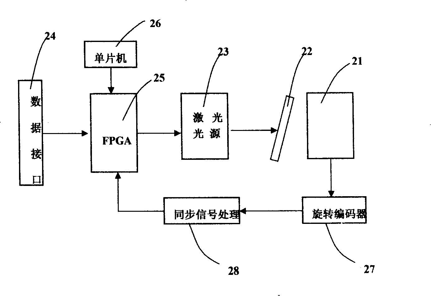
[0020] Such as figure 2 As shown, figure 2 It is a schematic block diagram of the laser imagesetter of the present invention. The laser imagesetter of this embodiment includes a drum 21 for fixing the film and rotatable around the axis; an optical fiber close-packed array 22 inclined to a certain angle with respect to the axis of the drum 21. The optical fiber close-packed array 22 includes 32 lines arranged in a straight line. Optical fiber; a laser light source 23 corresponding to each optical fiber in the optical fiber close-packed array 22; a data interface 24 for receiving image signals corresponding t...


PUM


Abstract

The invention relates to a correction method of a fiber compact array imaging and a laser imaging device where the method is applied; wherein, the fiber compact array comprises a plurality of fibers which are arranged along lines and inclined by a certain angle corresponding to the prearranged direction of an image plane. The correction method comprises that image signals which are respectively corresponding to all fibers in the fiber compact array are received; the image signals are respectively delayed in the shift register of an FPGA; all delay image signals drive the laser sources which are corresponding to all the fibers so as to image the image signals which are synchronously received on the image plane sequentially with prearranged interval through the fiber compact array. By adopting the method, the image signals which are synchronously received by the FPGA are delayed so as to lead the image signals to be output with prearranged interval and matched with the movement of the image plane in order to be imaged in the same line which is parallel to the prearranged direction, thus realizing the correction process; meanwhile, the invention has the advantages of high integrated level, easy realization, simple structure, fast operation speed, stable operation, low malfunction ratio, etc.

Description

【Technical Field】 [0001] The present invention relates to a correction method for optical fiber close-packed array imaging, and more particularly to a correction method for optical fiber close-packed array imaging based on FPGA and a laser imaging device using the method. 【Background technique】 [0002] The laser imaging devices of laser imagesetters that are currently widely used are divided into two types: helium-neon laser imaging and semiconductor laser imaging. In the semiconductor laser imaging system, a semiconductor laser is generally used as the light source, and the light emitted by the semiconductor laser is imaged on the image plane (film surface) through an optical lens by using a close-packed optical fiber array. Such as figure 1 As shown, in the Chinese invention patent application 200410028158.6 titled "Method and Device for Realizing Light Spots in Close-packed Optical Fiber Arrays", in order to overcome the excessively large spot spacing caused by the optical f...

Claims


Application Information

Patent Timeline
IPC IPC(8): B41B19/00B41B21/16B41J2/435
Inventor 高云峰苏美山
Owner HANS LASER TECH IND GRP CO LTD
Why Eureka
Try Eureka