
Coal mine down-hole positioning device and positioning method thereof

A technology of positioning device and positioning method, which is applied in the direction of mining equipment, positioning, measuring equipment, etc., and can solve the problems of low positioning accuracy, failure to detect the detected terminal, poor positioning accuracy, etc.

Inactive Publication Date: 2008-06-11
深圳市哲扬科技有限公司
View PDF0 Cites 10 Cited by
  • Summary
  • Abstract
  • Description
  • Claims
  • Application Information

AI Technical Summary

Problems solved by technology

[0002] At present, coal mine safety production has become one of the focuses of safety production. In coal mines with extremely complicated working conditions, it is often necessary to locate specific people or objects. At present, positioning algorithms based on existing technologies, such as RFID methods, in fact It cannot be regarded as a positioning algorithm in the strict sense. It can only judge whether the located terminal is "in" or "not in" around the detection device (reader), that is, there are only two states, "0" or "1", and one detection The radiation range of the device is a space with a radius of 50 meters. It can only judge whether the detected terminal is in this space, and the positioning accuracy is relatively poor.
If the radiation range is reduced, although the positioning accuracy can be improved, a new problem arises, that is, under the same number of detection devices (readers), the overall coverage of the detection area decreases, and most areas may not be detected at all. There is no signal coverage, so the presence of the detected terminal cannot be detected at all; this is a dilemma
In the existing technology, the technology or equipment to realize underground positioning in coal mines has technical defects such as outdated positioning methods, low sensitivity, low positioning accuracy, and poor safety. Timely and accurate positioning of objects or objects; the above-mentioned technical defects in the prior art have become a major technical problem to be solved urgently by those skilled in the art

Method used

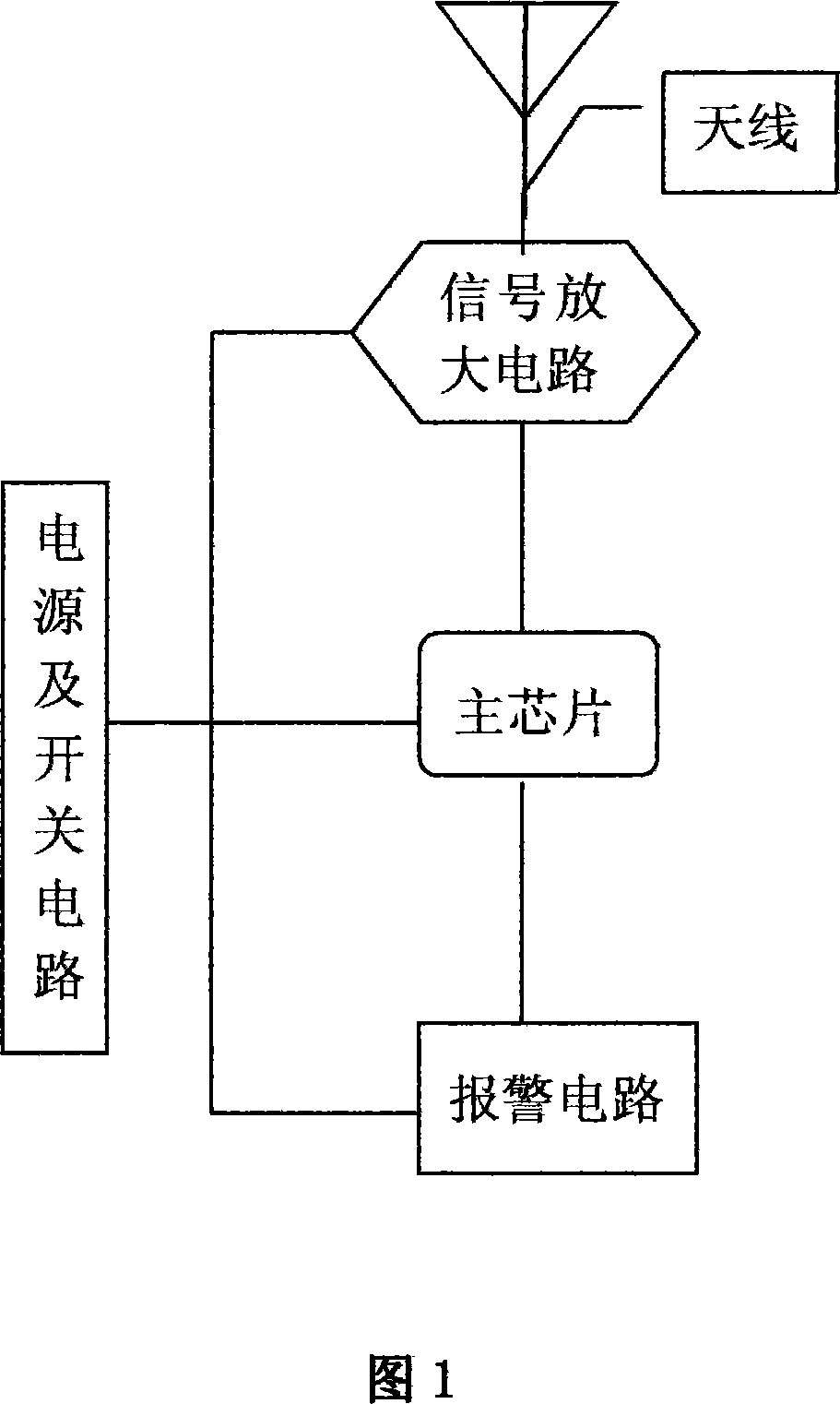

Image

  • Coal mine down-hole positioning device and positioning method thereof
  • Coal mine down-hole positioning device and positioning method thereof
  • Coal mine down-hole positioning device and positioning method thereof

Examples


Embodiment Construction

[0022] This embodiment is only a preferred embodiment of the present invention, and does not limit the scope of the present invention; in this embodiment, the locating device of the present invention is a locator.

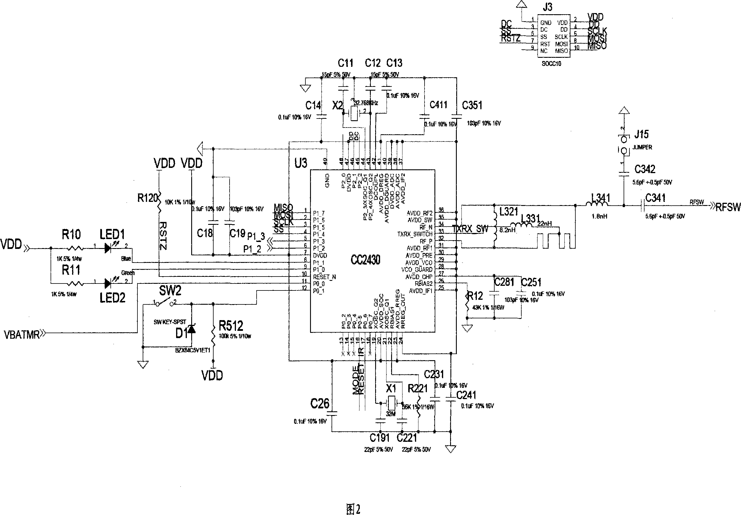
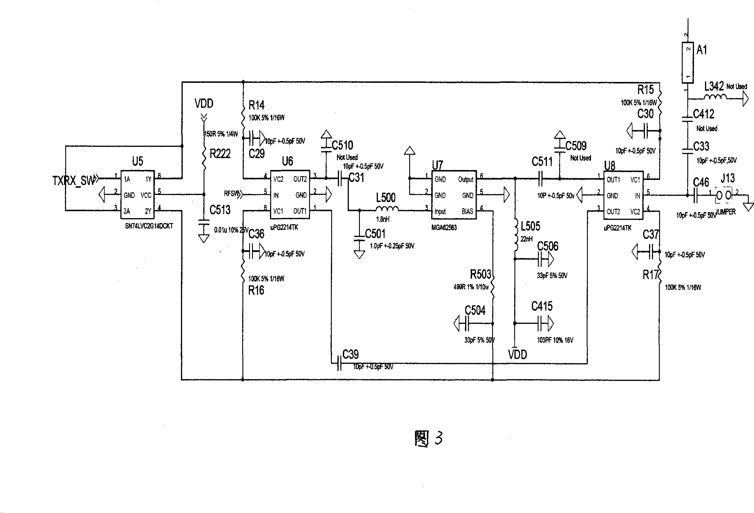
[0023] In conjunction with accompanying drawings 1 to 4, in an embodiment of the coal mine underground positioning device of the present invention, the power supply and the switch circuit include: a NAND gate circuit U11, a high-level LDO power chip U4, and a power button SW1; The circuit is connected to the I / O interface of the main chip CC2430. The power button SW1 is connected to the NAND gate circuit U11; the current limiting resistor R510 is set between the NAND gate circuit U11 and the power supply, and is connected to the LDO power chip U4 through the fuse F1, the current limiting resistor R3, and the resistor R4, and through R27, R28 Connect to the I / O port of CC2430 for power detection. In the non-working state, the NAND gate circuit U11 outputs a low lev...


PUM


Abstract

The invention discloses a coal mine underground locating device and the locating method, which aims to overcome the technical problems of the low-sensitivity and low-precision locating by the locating device and locating method in prior art. The invention provides a locating device and the locating method with high sensitivity and high locating precision, which is safer and more reliable; the locating device in the invention is provided with a shell, on which equipped with a circuit board. The circuit board is mounted with a power source and the switch circuit. The power source and the switch circuit are connected with the interface I / O of the main chip which is connected with a signal amplifier circuit and a warning circuit; the signal amplifier circuit is connected with the technical scheme of antenna; separately calculates the distance between the signal intensity and the two communication base stations according to the signal intensity by testing the signal intensity from at least two communication base stations, and then calculates the locating method which accords with the coordinate point to the distance of the two base stations. The locating device and the locating method provided in the invention has high locating precision and high sensitivity, which is applicable to the safe production of the coal mine underground.

Description

technical field [0001] The invention relates to a positioning device, in particular to a positioning instrument and a positioning method for positioning the position in a coal mine underground. Background technique [0002] At present, coal mine safety production has become one of the focuses of safety production. In coal mines with extremely complicated working conditions, it is often necessary to locate specific people or objects. At present, positioning algorithms based on existing technologies, such as RFID methods, in fact It cannot be regarded as a positioning algorithm in the strict sense. It can only judge whether the located terminal is "in" or "not in" around the detection device (reader), that is, there are only two states, "0" or "1", and one detection The radiation range of the device is a space with a radius of 50 meters. It can only judge whether the detected terminal is in this space, and the positioning accuracy is relatively poor. If the radiation range is...

Claims


Application Information

Patent Timeline
Patent Type & Authority Applications(China)
IPC IPC(8): G01S5/12G01S11/06H04B1/38E21F17/18
Inventor 季文涛许亚明陈士兵迟钟黎雪梅
Owner 深圳市哲扬科技有限公司
Learn More