A dual-frequency ultra-thin highly directional resonance cavity antenna

A resonant cavity antenna, high directional technology, applied in resonant antennas, resonant antenna parts, antennas and other directions, can solve the problems of single-frequency operation, limitation, etc., and achieve the effect of high gain and high directivity

Active Publication Date: 2011-06-22
TONGJI UNIV
View PDF0 Cites 0 Cited by
  • Summary
  • Abstract
  • Description
  • Claims
  • Application Information

AI Technical Summary

Problems solved by technology

But this kind of resonant cavity has a disadvantage, that is, it can only work at a single frequency.
For the electromagnetic waves of vertical and horizontal polarization, the response is exactly the same, which has great limitations in the field of multi-channel microwave communication that is developing day by day.

Method used


Image

  • A dual-frequency ultra-thin highly directional resonance cavity antenna
  • A dual-frequency ultra-thin highly directional resonance cavity antenna
  • A dual-frequency ultra-thin highly directional resonance cavity antenna

Examples


Embodiment 1

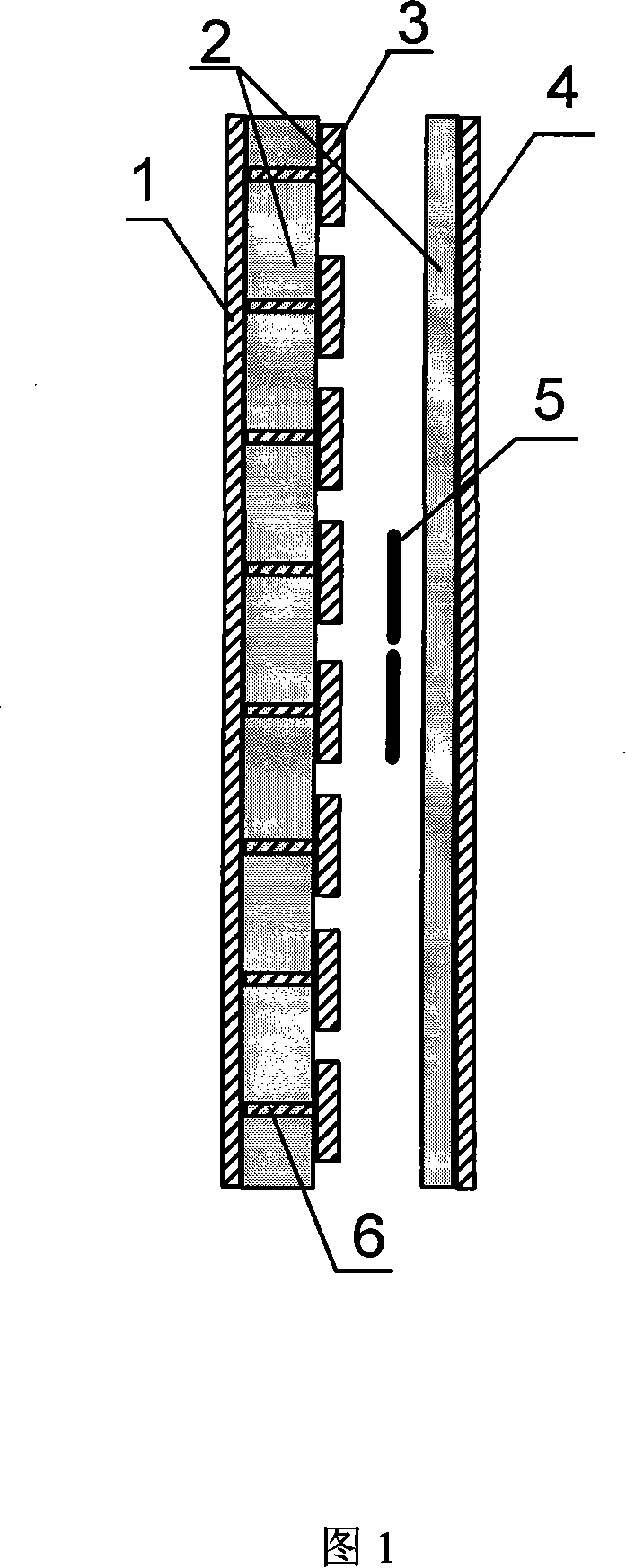
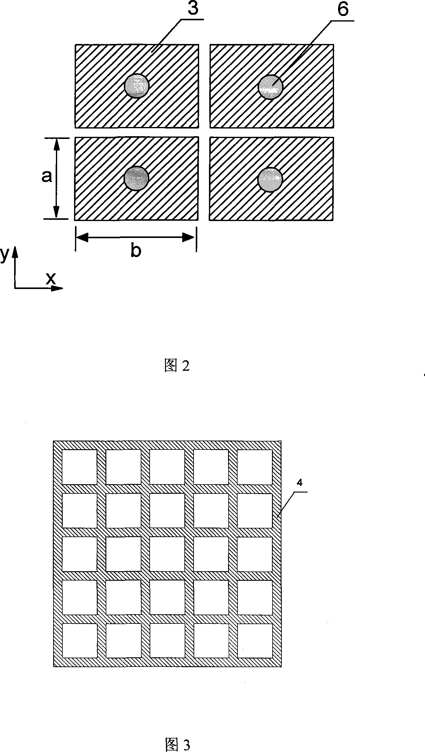
[0020] Please refer to the attached figure 1 , with figure 2 .

[0021] The present invention comprises a high-impedance surface, a metal grid layer 4 and a microwave feed source 5 between the two, the metal grid layer 4 is a common commercially available single-sided printed circuit board made by itself, and its dielectric layer 2 has a thickness of 0.8 mm. On the surface of the commercially available single-sided printed circuit board, a metal grid with a period smaller than the operating frequency is self-produced, which acts as a common reflector, but this reflector allows a small amount of electromagnetic wave transmission. The microwave feed source 5 is a commercially available dipole antenna or monopole antenna or other commonly used microwave feed sources. The high-impedance surface is an anisotropic high-impedance surface, and the anisotropic high-impedance surface is composed of a metal layer 1 on the lower surface, a dielectric layer 2 in the middle, and an arra...

Embodiment 2

[0023] The present invention whose size is 200X200 square millimeters is made, except that the anisotropic high-impedance surface is composed of the metal layer 1 on the lower surface, and the anisotropic resonant unit 3 on the upper surface is composed of an I-shaped structure array, and the microwave feed source 5 adopts a Except for the monopole antenna at about 10 GHz, the rest of the structure is the same as that of Embodiment 1.

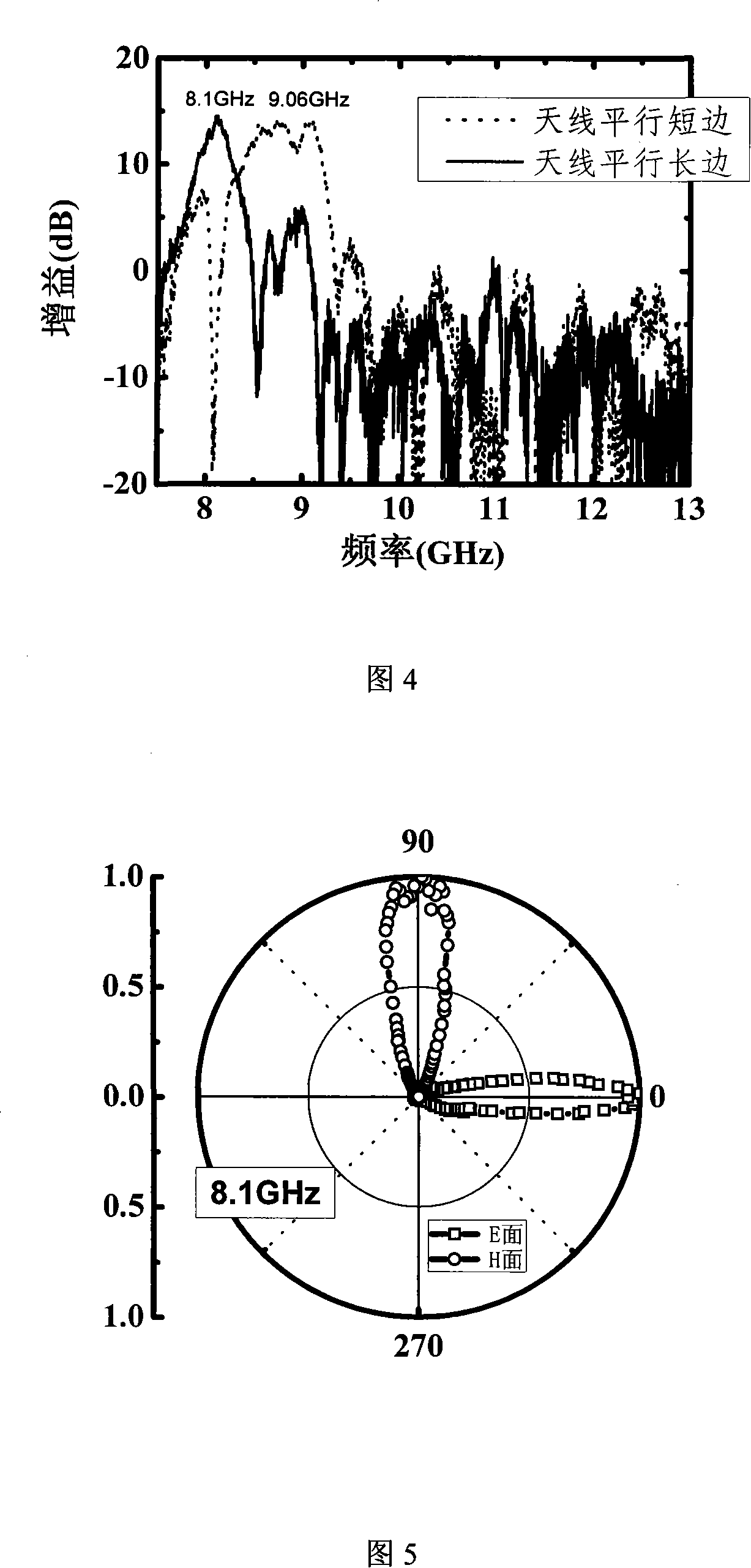
[0024] The dipole antenna's vibrator is parallel to the I-shaped parting and perpendicular to the I-shaped parting to measure the gain spectrum and pattern of the antenna. The gain spectrum of the measured forward radiation is that when the antenna is parallel to the I-shaped and perpendicular to the I-shaped, we get the maximum gain values ​​of 4.5GHz and 6.1GHz. Corresponding to two different operating frequencies of parallel and vertical polarization respectively. The directivity diagrams of these two frequencies were measured, and the resu...


PUM


Abstract

The invention relates to a dual-frequency ultra-thin high directional resonator antenna which relates to a dual-frequency resonator antenna. The invention comprises a high impedance surface, a metal grid layer (4) and a microwave feed source (5) between the high impedance surface and the metal grid layer. The metal grid layer (4) is of a self-made single-side printed circuit board, and the microwave feed source (5) is of a dipole antenna or a monopole antenna or other microwave feed sources. The invention is characterized in that the high impedance surface is an anisotropy high impedance surface which is composed of a metal layer (1) at the lower surface, an intermediate medium layer (2) and an anisotropy resonance unit (3) in an array, or in the array, the resonance unit (3) is connectedwith the metal layer (1) by using a plated through hole (6). The anisotropy resonance unit (3) has design quantitative metal foils with a rectangle structure, an H-shaped structure or a Hilbert type curve structure, and intervals are arranged between the metal foils. The invention has the advantages of small thickness less than Lambada / 10, dual-frequency work, high directional radiation and highgain ability.

Description

technical field [0001] A dual-frequency ultrathin highly directional resonant cavity antenna relates to a dual-frequency resonant cavity antenna. Specifically, it means that dual-frequency highly directional radiation can be achieved, the thickness is thinner than conventional Fabry-Perot resonators, the structure is compact, and the dual-frequency resonator antenna structure is simple to manufacture. Background technique [0002] Due to the long communication distance and strong anti-interference ability, highly directional antennas are widely used in the field of microwave communication. The radiation pattern of the resonant cavity antenna is highly directional, so it can be used as a highly directional antenna. Among existing resonator antennas, Fabry-Perot resonators are widely used. The resonant cavity is composed of two reflective surfaces and a microwave feed source. One reflective surface is an ideal reflective surface, and the other reflective surface can allow a ...

Claims


Application Information

Patent Timeline
Patent Type & Authority Patents(China)
IPC IPC(8): H01Q9/04H01Q15/14H01Q19/10H01Q9/06
Inventor 李宏强魏泽勇武超魏雯婕
Owner TONGJI UNIV
Why Eureka
Try Eureka