
Semiconductor package structure

A packaging structure, semiconductor technology, applied in the direction of semiconductor devices, semiconductor/solid-state device parts, electric solid-state devices, etc., can solve the problems of increasing the probability of chip damage, increasing the size of the packaging structure, inconvenience, etc., to reduce chip damage The probability of electromagnetic interference shielding and the effect of overcoming electromagnetic interference

Active Publication Date: 2008-05-28
ADVANCED SEMICON ENG INC
View PDF0 Cites 14 Cited by
  • Summary
  • Abstract
  • Description
  • Claims
  • Application Information

AI Technical Summary

Problems solved by technology

However, this prior art must seal the two chips together after the related structures of the two chips are completed, so that the two chips are exposed to the outside for too long, thus increasing the probability of chip damage
In addition, this existing technology will increase the size of the package structure it makes, and it is not easy to meet the requirements of miniaturization
[0004] It can be seen that the above-mentioned existing semiconductor packaging structure obviously still has inconvenience and defects in the use of product structure, and needs to be further improved urgently.
In order to solve the above-mentioned problems, the relevant manufacturers have tried their best to find a solution, but no suitable design has been developed for a long time, and the general products do not have a suitable structure to solve the above-mentioned problems. This is obviously related. The problem that the industry is eager to solve

Method used


Image

  • Semiconductor package structure
  • Semiconductor package structure
  • Semiconductor package structure

Examples


Embodiment Construction

[0032] In order to further explain the technical means and effects of the present invention to achieve the intended purpose of the invention, the following describes the specific implementation, structure, steps, features and the semiconductor package structure of the present invention with reference to the drawings and preferred embodiments. Efficacy, as detailed below.

[0033] The foregoing and other technical content, features, and effects of the present invention will be clearly presented in the following detailed description of the preferred embodiment with reference to the drawings. Through the description of the specific embodiments, it is possible to gain a more in-depth and specific understanding of the technical means and effects adopted by the present invention to achieve the predetermined purpose. However, the accompanying drawings are only for reference and explanation purposes, and are not used for the present invention. Be restricted.

[0034] Although the present ...


PUM


Abstract

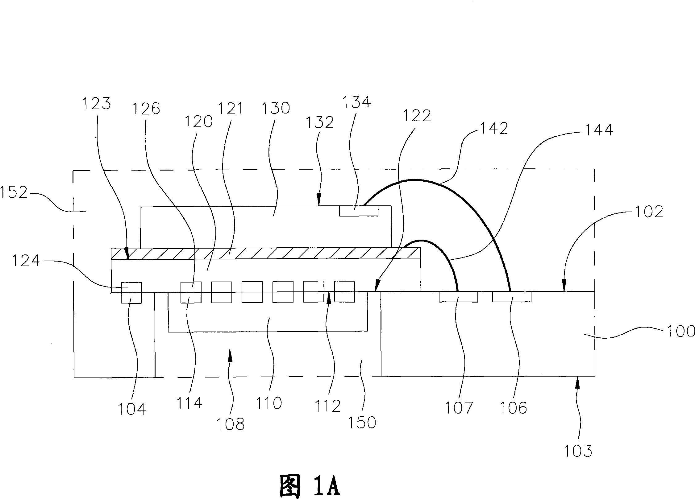
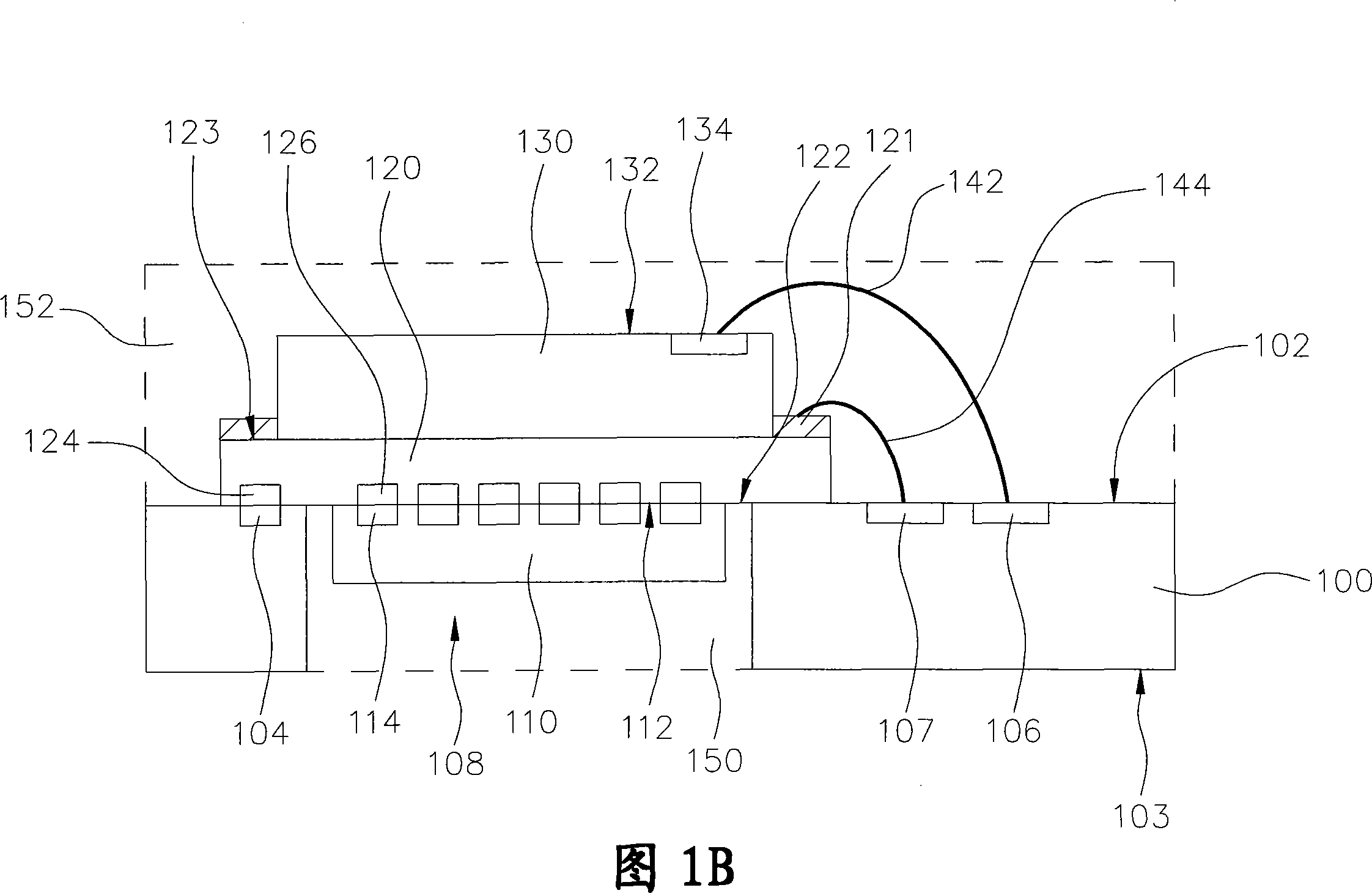
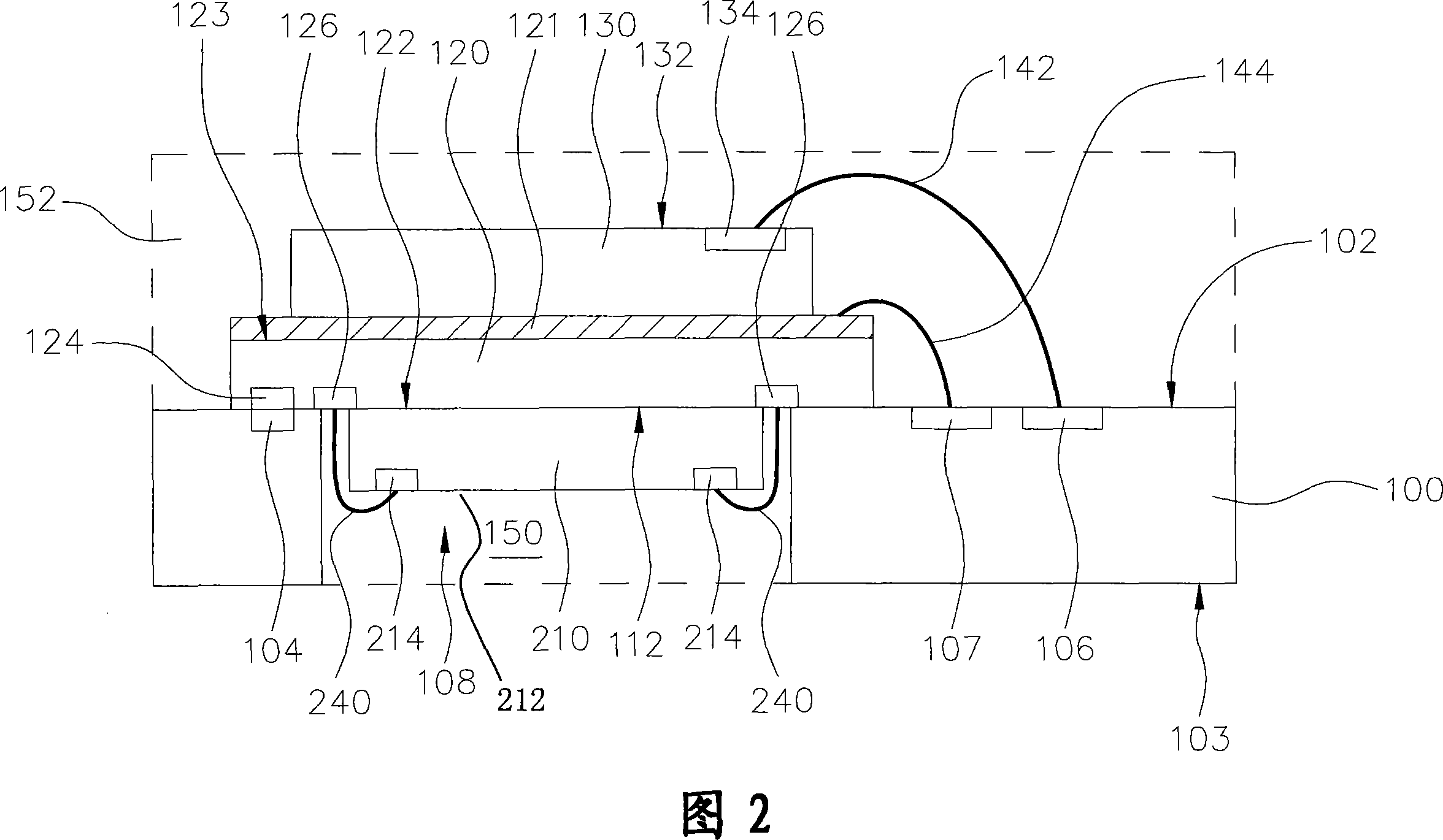
A semiconductor package structure and a method for manufacturing the same are disclosed. The semiconductor package structure includes a substrate, an interposer (such as a circuitry laminate), a metal layer formed on the interposer, a first chip and a second chip, wherein the interposer is disposed on the substrate and covers at least a portion of an opening of the substrate, thereby defining a space for receiving the first chip, and the second chip is disposed on the metal layer or the interposer. The metal layer is electrically connected to the substrate and grounded. The first chip is electrically connected to the substrate.

Description

Technical field [0001] The present invention relates to a semiconductor packaging structure, in particular to a semiconductor packaging structure with electromagnetic interference (EMI) shielding effect. Background technique [0002] With the increasing demand for miniaturization and high operating speed, semiconductor package structures with multiple semiconductor chips (ie, multi-chip package structures) have become more and more attractive in many electronic devices. The multi-chip package structure can combine the processor, memory (memory, storage medium, memory, memory, etc., hereinafter referred to as memory) and logic chip in a single package structure to connect the printed circuit board The resulting system operation speed limit is minimized. In addition, the multi-chip package structure can also reduce the length of the connection lines between the chips, and can reduce the signal (ie, signal) delay and access time. [0003] However, especially for high-frequency compo...

Claims


Application Information

Patent Timeline
Patent Type & Authority Applications(China)
IPC IPC(8): H01L25/00H01L25/065H01L25/18H01L23/488H01L23/552
CPCH01L2924/1532H01L2225/06572H01L2224/16145H01L24/48H01L25/0657H01L2225/06527H01L2225/06517H01L2224/32145H01L2225/0651H01L2225/06555H01L23/13H01L2224/48091H01L2224/73265H01L2924/3025H01L2224/04042H01L2924/181H01L2224/48145H01L2924/00014H01L2924/00012H01L2224/45099H01L2224/45015H01L2924/207H01L2924/00
Inventor 金炯鲁
Owner ADVANCED SEMICON ENG INC
Learn More