
Optical thin sheet with reinforced structur

A technology of optical flakes and structures, applied in optics, nonlinear optics, coatings, etc., can solve problems such as defect rate and poor transmittance of glass substrates

Inactive Publication Date: 2008-05-14
ETERNAL MATERIALS CO LTD
View PDF1 Cites 10 Cited by
  • Summary
  • Abstract
  • Description
  • Claims
  • Application Information

AI Technical Summary

Problems solved by technology

However, although the inclusion of an inorganic layer in the protective layer can improve the adhesion between the protective layer and the glass substrate, it may cause the light transmittance of the glass substrate to deteriorate, and an additional process is required due to the inclusion of the inorganic layer. It may also increase its defect rate

Method used


Image

  • Optical thin sheet with reinforced structur
  • Optical thin sheet with reinforced structur
  • Optical thin sheet with reinforced structur

Examples


preparation example 1

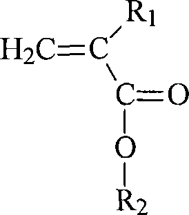
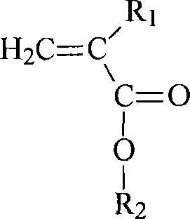
[0064] The polyacrylate resin of Example 1 was prepared with monomers, solvents and appropriate initiators in different proportions, and the preparation conditions are shown in Table 1:

[0065] Table 1

[0066] Mixture

Embodiment 1

[0068] The polyacrylate resin prepared above is reacted with a hardener and other solvents to prepare the thermosetting resin of the protective layer of the present invention. The preparation conditions are shown in Table 2:

[0069] Table 2

[0070] Raw materials

preparation example 2-3

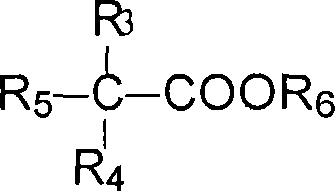
[0072] The fluorocarbon resin of Example 2 was prepared with different ratios of monomers, solvents, and appropriate initiators. The preparation conditions are shown in Table 3:

[0073] table 3

[0074] Preparation Example 2


PUM


Abstract

The invention provides an optical wafer, which comprises a basis material and at least one protection layer. The protection layer is positioned on at least one surface of the basis material and has an organic layer, and the organic layer comprises a thermosetting resin used for increasing the basis material toughness. The protection layer and the basis material have good adherence with each other. The optical wafer protected by the protection layer can not produce warp and has high optical transparency.

Description

Technical field [0001] The present invention relates to an optical sheet, especially an optical sheet with a reinforced structure. Background technique [0002] At present, electronic products have developed towards lightness and thinness. Since cathode ray tubes (CRT) cannot achieve lightness and thinness and low power consumption, liquid crystal displays (LCD), plasma display panels (PDP), and electroluminescence are gradually being used. Display (electroluminescent display; ELD), vacuum fluorescent display (vacuum fluorescent display) and other flat-panel displays are replaced. Among them, the liquid crystal display has become the mainstream of the market due to its advantages of high image quality, low radiation, low power consumption, and better space utilization. [0003] The method used to make the liquid crystal display thinner and lighter is nothing more than thinning the glass substrate that accounts for a certain weight in the liquid crystal display, or replacing the g...

Claims


Application Information

Patent Timeline
IPC IPC(8): G02F1/1333C08J7/04C08L33/04C08L69/00C08L25/06C08L79/08C08L67/00
Inventor 叶茂荣李金木张俊雄
Owner ETERNAL MATERIALS CO LTD
Learn More