
Maximum density projection generating method for medical image

A technology of maximum density and medical imaging, which is applied in the field of computing, can solve the problems of large storage space for computation, and achieve the effect of reducing computation time, fewer computation steps, and reducing computation

Active Publication Date: 2008-05-07
LANWON TECH
View PDF0 Cites 3 Cited by
  • Summary
  • Abstract
  • Description
  • Claims
  • Application Information

AI Technical Summary

Problems solved by technology

[0022] The purpose of the present invention is to provide a high-efficiency method for generating maximum density projection of medical images to solve the problems of large amount of computation and required storage space in the prior art

Method used


Image

  • Maximum density projection generating method for medical image
  • Maximum density projection generating method for medical image
  • Maximum density projection generating method for medical image

Examples


Embodiment 1

[0073] according to Figure 5 , the original image data body composed of multiple parallel image frames, the image frames sequentially include the first image frame, the second image frame, ..., and the nth image frame, forming a width, height, and thickness respectively W, For the data volumes of H and L, the adjacent three sides of the data volume coincide with the X-axis, Y-axis and Z-axis of the three-dimensional space respectively, and the data volume forms an axial plane (X-axis*Y-axis), a radial plane ( Y-axis*Z-axis) and coronal plane (Z-axis*X-axis).

[0074] Such as Figure 5 As shown, the present invention uses the projection of one of the image frames on the projection surface as a mapping template, and the projection of other image frames on the projection surface is based on the mapping template. After translation processing, it overlaps with the mapping template to perform the maximum density MIP of medical images Projection processing, since all image frames ...

Embodiment 2

[0131] In the above-mentioned embodiments, the full-precision MIP processing flow for the original image data volume is embodied. For practical applications, in order to meet the real-time display of projection results, the present invention may need to adapt to the change of projection direction, and the generation of MIP images must be The time is strictly limited, and if it exceeds a certain generation time, there will be a sense of hysteresis.

[0132] Such as Figure 11 As shown, another specific control flow of the present invention is as follows:

[0133] 1) To determine whether to perform full-precision MIP processing, perform the following operations:

[0134] 1a) If full-precision MIP processing is performed, then process according to the full-precision MIP process, that is, according to step 1-step 13 in embodiment 1, until step 11);

[0135] 1b) Otherwise, according to the set pixel total threshold T (in this embodiment, the pixel total threshold T is set to 4M) ...


PUM


Abstract

The invention relates to a calculated medical image maximum density projection generation method, which comprises the following steps: step A, for an initial image data volume formed by a plurality of parallel image frames, the projection of one of the image frames on a projection plane is used as the mapping template; step B, after translation processing, the projection of other image frames on the projection plane is overlapped with the mapping template, and medical image maximum density projection processing is performed; step A comprises the following steps: step A1, the planar parameters and MIP image coordinate parameters of the projection plane are created, and the projection of the image frames on the projection plane is used as the mapping template; step A2, a mapping table is created; step B comprises the following steps: step B1, medical image maximum density MIP processing to each point of the first image frame is performed according to the mapping table; step B2, for the subsequent image frames, a new temporary mapping table is formed; step B3, corresponding medical image maximum density MIP processing to the subsequent image frames is performed according to the new mapping table, and the MIP image is dynamically refreshed to generate the final MIP image. The invention has the advantages of small operation quantity and small middle storage space requirement, thereby meeting real-time requests.

Description

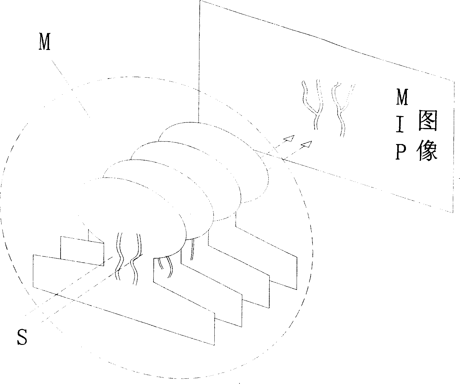
technical field [0001] The invention relates to calculation, in particular to a method for generating medical image maximum density projection. Background technique [0002] The maximum intensity projection technique (MIP), as a visualization three-dimensional technique, has been effectively applied to the visualization of blood vessels, bones and soft tissues obtained from magnetic resonance imaging MR and computed tomography CT data due to its simple and feasible advantages. It can play an important auxiliary role in the diagnosis of diseases such as cerebrovascular, cardiovascular and tumor tissues. [0003] Such as figure 1 As shown, the essence of the MIP algorithm is to use a bundle of parallel rays S to pass through a volume M from a certain angle, and find the maximum value on each ray. The image composed of these maximum values ​​is called a MIP image. [0004] The MIP algorithm is an algorithm with a relatively large amount of calculation. Its basic principle req...

Claims


Application Information

Patent Timeline
Patent Type & Authority Applications(China)
IPC IPC(8): G06T15/20A61B6/03A61B5/055
Inventor 蔡春辉刘兵全柳伟陈闽峰
Owner LANWON TECH
Learn More