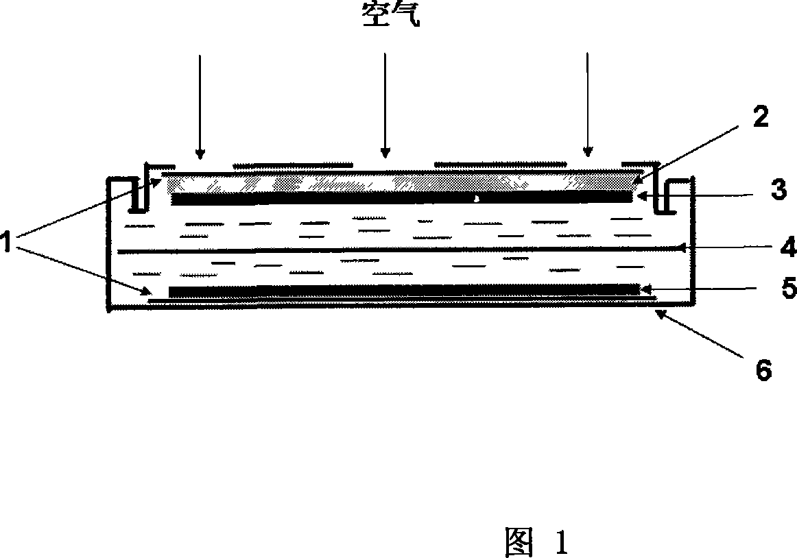
Asymmetric secondary air fuel battery
A secondary air and fuel cell technology, applied in the field of electrochemical energy storage, can solve the problems of difficult commercialization of batteries and high battery costs
- Summary
- Abstract
- Description
- Claims
- Application Information
AI Technical Summary
Problems solved by technology
Method used
Image
Examples
Embodiment 1
[0016] Take LiTi 2 (PO 4 ) 3 As a negative electrode material, the electrode preparation method is as follows: conductive agent (acetylene black): binder (PTFE): LiTi 2 (PO 4 ) 3 = 5: 10: 85 ratio mixing slurry, rolling into film, and pressing it onto foamed nickel mesh to form negative electrode film. Positive electrode adopts the active carbon that has loaded manganese tetraoxide as catalyst, and catalytic layer preparation method is with conductive agent (acetylene black): binding agent (PTFE): active carbon (supporting 20wt% manganese tetraoxide)=5: 10: 85 Mix the slurry in proportion, roll it into a film, and cut it into a pole piece of a certain size. The gas diffusion layer is formed by mixing acetylene black: binder = 60:40 into a slurry and rolling it into a film. The gas diffusion layer and the catalyst layer are sequentially pressed onto the foamed nickel mesh to form the positive electrode membrane. The electrolyte is 1M NaOH gel electrolyte, which is prepar...
Embodiment 2
[0018] The negative electrode is carbon-coated LiTi 2 (PO 4 ) 3 , and its synthesis method is as follows: 3g LiTi 2 (PO 4 ) 3 Be dispersed in the aqueous solution that contains 2wt%PVA (polyvinyl alcohol) in 100ml, stir at high temperature and evaporate the solution to dryness, put into tube furnace under N 2 Calcination at 900℃ under atmosphere to obtain carbon-coated modified LiTi 2 (PO 4 ) 3 The composite material has a carbon content of 36 wt% as tested by thermogravimetric analysis. LiTi coated with carbon 2 (PO 4 ) 3 is the negative electrode material, and the rest are the same as in Example 1, and the battery is prepared according to the steps and conditions in Example 1. at 5mA / cm 2 Under the same current density, the charging voltage platform remains unchanged, still around 1.2V, and the initial charging capacity is 83mAh / g; the discharging platform is at 0.66V, and the initial discharging capacity is 74mAh / g. The coulombic efficiency and cycle performanc...
Embodiment 3
[0020] Adopt the method for gas phase deposition to the LiTi of carbon coating in embodiment 2 2 (PO 4 ) 3 Carry out further carbon coating modification, its synthetic method is: with the LiTi of carbon coating in embodiment 2 2 (PO 4 ) 3The material is the bulk, placed in a tube furnace. Toluene is used as the carbon source, Ar gas is used as the gas source, the gas flow rate is controlled, and the toluene vapor is blown into the tube furnace, during which the temperature of the tube furnace is programmed to rise to the reaction temperature of 900°C. When the furnace temperature reaches the required temperature, the furnace temperature is controlled. 300min at the reaction temperature. After being cooled, it is ground to obtain the desired carbon-coated LiTi 2 (PO 4 ) 3 Material. with PVA-coated LiTi 2 (PO 4 ) 3 In contrast, the vapor deposition method can uniformly deposit a layer of nanometer-thick graphitized carbon layer on the particle surface, ensuring that ...
PUM
 Abstract
Description
Claims
Application Information
 - R&D
- Intellectual Property
- Life Sciences
- Materials
- Tech Scout
- Unparalleled Data Quality
- Higher Quality Content
- 60% Fewer Hallucinations
Browse by: Latest US Patents, China's latest patents, Technical Efficacy Thesaurus, Application Domain, Technology Topic, Popular Technical Reports.
© 2025 PatSnap. All rights reserved.Legal|Privacy policy|Modern Slavery Act Transparency Statement|Sitemap|About US| Contact US: help@patsnap.com

