


Quick Research
Generate reliable direction feasibility study reports for your R&D in just a few steps.

Technical Q&A
Discover and master advanced knowledge NOW. Basics, ideas, possibilities, all at once.

Find Solutions
As an expert in R&D theories, this can generate solutions to your technical problems instantly.

Evaluate Feasibility
Analyze your overall solution with one click, know your potential R&D risks in advance.

Monitor Landscape
Get weekly tech updates, stay abreast of the latest tech innovations and key insights.
Micro fluid control array protein chip and its usage method
A protein chip and microfluidic technology, applied in the field of protein chips, can solve the problems of insufficient operation and low degree of automation, and achieve the effects of reducing production costs, easy operation, and rapid analysis
- Summary
- Abstract
- Description
- Claims
- Application Information
AI Technical Summary
Problems solved by technology
Method used
Image


Examples
Embodiment 1
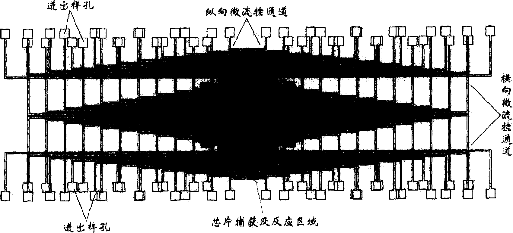
[0030] 1. Using a silicon wafer with photoetched patterns as a positive mold and polydimethylsiloxane (PDMS) as a substrate, fabricate 20 lateral microfluidic channels (channel width 100 microns, thickness 3mm) The PDMS substrate, that is, the microfluidic channel sheet; after the PDMS substrate is peeled off from the mold, use a puncher (diameter 1mm) to punch a hole (diameter 0.6-0.8mm) at the end mark of the microchannel as the inlet and outlet These holes are used to insert microfluidic tubing, such as inlet and outlet capillaries, into the microchannel.
[0031] 2. Two pieces are processed by conventional methods (any one of them contains a microfluidic pipeline channel, which is used for the passage of liquid inlet and outlet thin tubes, and the position is the same as figure 1 The inlet and outlet holes of the middle PDMS channel sheet correspond to each other. ) plexiglass as a clip, reversibly seal the PDMS substrate containing the transverse microchannel and the sil...
Embodiment 2
[0034] 1. Using a silicon wafer with photoetched patterns as a positive mold and polydimethylsiloxane (PDMS) as a substrate, fabricate 50 longitudinal microfluidic channels (channel width 50 microns, thickness 5 mm) PDMS substrate; after the PDMS substrate is peeled off from the mold, holes are punched at the end mark of the microchannel with a puncher.
[0035] 2, by the method similar in embodiment 1 step 2, use two pieces of processed plexiglass as clips, the PDMS substrate containing the longitudinal microchannel and the gold-plated glass slide (manufacturer, GENEFLUIDICS company product) as the chip substrate Perform reversible sealing, and connect the chip to a microinjection pump through a microplastic tube.
[0036] 3. Prepare 9 target protein nucleic acid aptamer assembly solutions No. 1-9 (concentrations: 1×10 -10 M, 5×10 -10 M, 1×10 -9 M, 5×10 -9 M, 1×10 -8 M, 5×10 -8 M, 1×10 -7 M, 5×10 -7 M, 1×10 -6 M, the nucleic acid aptamer is Shanghai Sangon Bioenginee...
Embodiment 3
[0038] 1. Prepare 20 PDMS substrates with longitudinal microfluidic channels (100 microns in channel width and 7 mm in thickness) according to the method of step 1 in Example 1, and combine the PDMS substrate with the longitudinal microchannels with the immunoglobulin obtained in Example 1 The protein-assembled chip is reversibly sealed, and the chip is connected to a micro-injection pump through a micro-plastic tube. Such as figure 1 As shown, the two layers of microchannels assembled on the microfluidic array protein chip are vertically crossed in the central area of the chip.
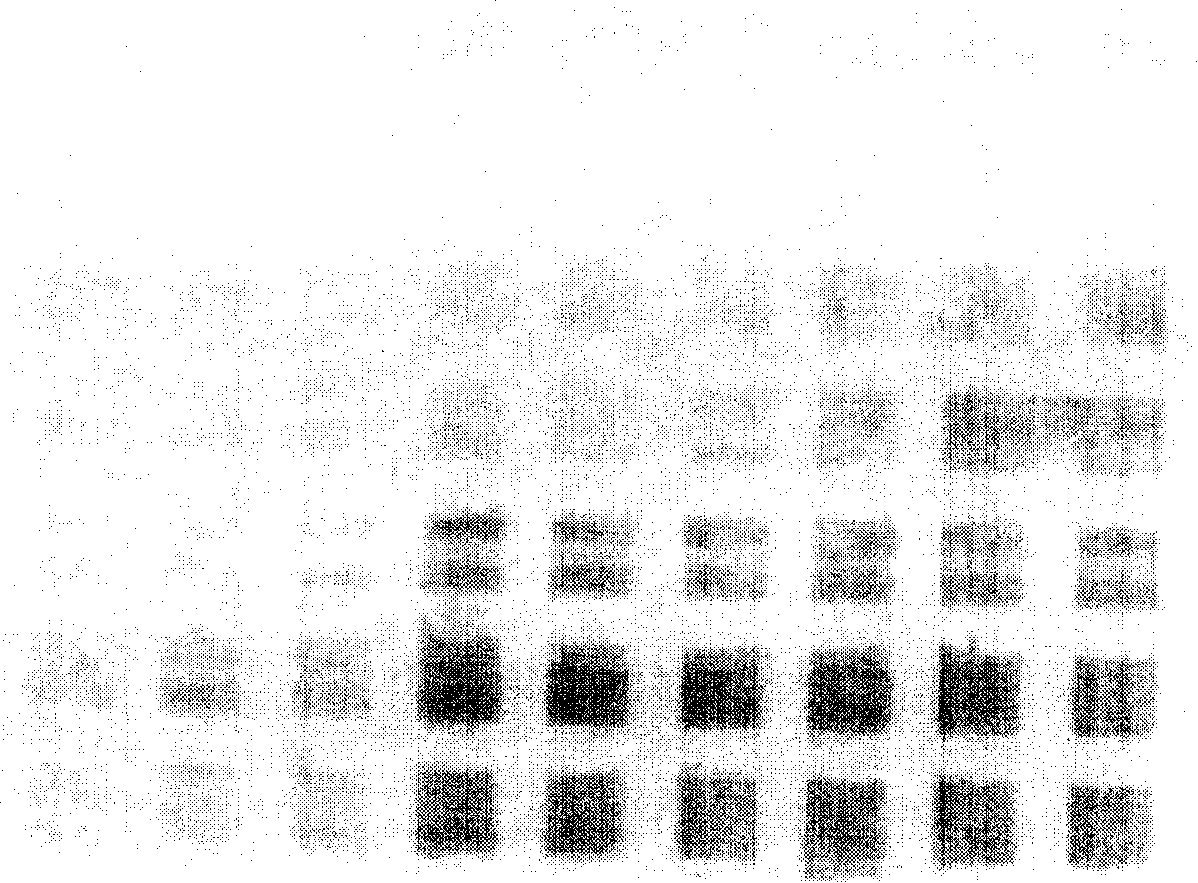
[0039] 2, 9 groups of concentration (10nM) identical sample solutions (goat anti-mouse immunoglobulins on the surface of gold nanoparticles) containing goat anti-mouse immunoglobulin (manufacturer, U.S. FITZGERALD company product) of 15nm nano-gold markers Assembled, the method refers to Nam, JM etc., "Science" volume 301 page 1884) at a speed of 2 microliters / hour through the microfluidic channel...
PUM
| Property | Measurement | Unit |
|---|---|---|
| thickness | aaaaa | aaaaa |
| thickness | aaaaa | aaaaa |
| width | aaaaa | aaaaa |
Abstract
Description
Claims
Application Information
 - R&D Engineer
- R&D Manager
- IP Professional
- Industry Leading Data Capabilities
- Powerful AI technology
- Patent DNA Extraction
Browse by: Latest US Patents, China's latest patents, Technical Efficacy Thesaurus, Application Domain, Technology Topic, Popular Technical Reports.
© 2024 PatSnap. All rights reserved.Legal|Privacy policy|Modern Slavery Act Transparency Statement|Sitemap|About US| Contact US: help@patsnap.com