
Composite heat dissipation device, cooling unit, cooling device and assembling body

A heat dissipation device and cooling unit technology, applied in coolers, water shower coolers, household refrigeration devices, etc., can solve the problems of increased number of parts and assembly man-hours, damage to rotating shafts and blades, and high cost of cooling devices. The effect of reducing parts cost, changing the cooling capacity, and reducing the number of manufacturing man-hours

Active Publication Date: 2008-03-26
HITACHI METALS LTD
View PDF2 Cites 7 Cited by
  • Summary
  • Abstract
  • Description
  • Claims
  • Application Information

AI Technical Summary

Problems solved by technology

For this reason, it is necessary to increase the radius of the fan and install multiple fans, but if the radius of the fan becomes larger, the noise during operation will increase
In addition, if multiple fans are installed in parallel, the fans will suck air from each other, resulting in uneven air intake (so-called drift phenomenon), and uneven stress will be repeatedly applied to the rotating shaft or blades of the fan, resulting in damage to the rotating shaft and blades. possibility of
[0005] Also, in the structure in which a fan is installed on the upper part of the device, (a) because the distance between the upper part and the lower part of the condenser and the fan is different, there is a difference in the flow rate of the outside air passing through the upper part and the lower part of the condenser, so not only the cooling efficiency is low; (b) Since it is necessary to form a closed space (chamber) between the fan and the condenser from the standpoint of cooling performance, it is necessary to provide a bottom plate between the cooling tower and the cooler unit, or to separate the sides of the cooling tower and Side panels are installed to isolate the outside air
Therefore, the number of parts and the number of assembly man-hours increase, and the cost of the cooling device increases

Method used


Image

  • Composite heat dissipation device, cooling unit, cooling device and assembling body
  • Composite heat dissipation device, cooling unit, cooling device and assembling body
  • Composite heat dissipation device, cooling unit, cooling device and assembling body

Examples


no. 1 approach

[0048] (A) Structure of cooling device

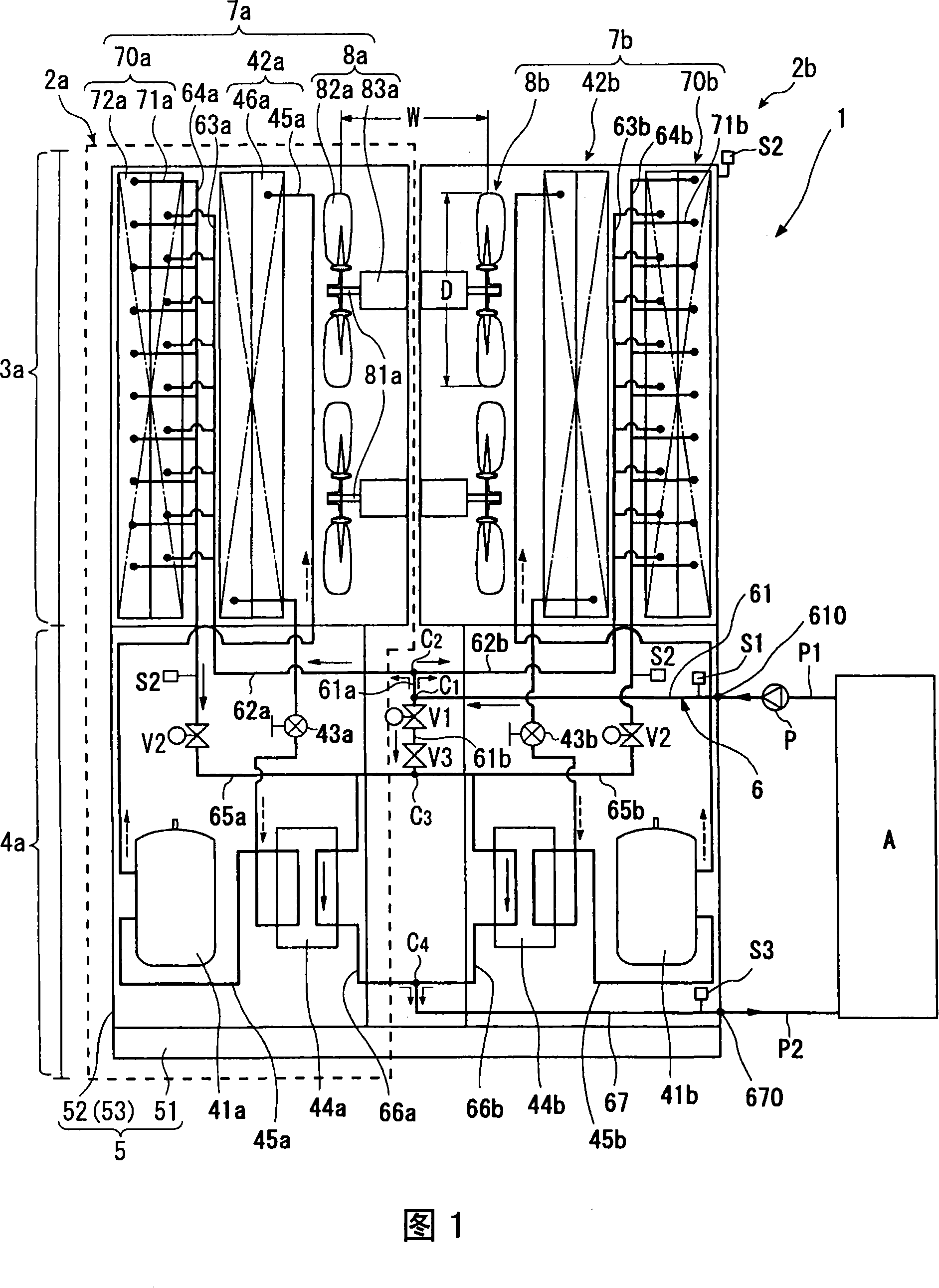
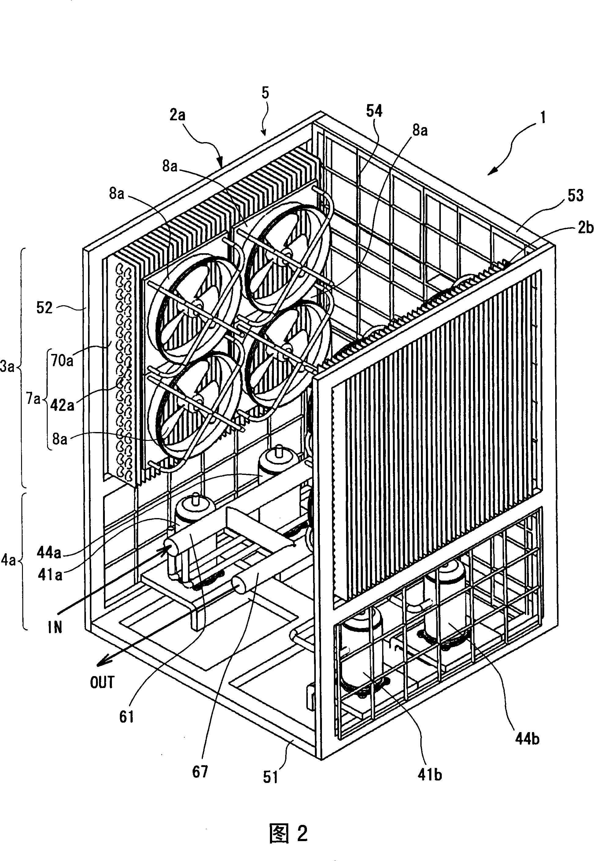
[0049] 1 and 2 are diagrams respectively showing an internal structure and an external appearance of a cooling device according to a first embodiment of the present invention. The cooling device 1 includes a pair of cooling units 2a, 2b for cooling a fluid to be cooled (for example, warm water) sent from an external device (not shown) to near room temperature and then sending it back to the external device. In FIG. 1 , one cooling unit 2 a is surrounded by a dotted line, and the solid arrows indicate the flow direction of the fluid to be cooled, and the dotted arrows indicate the flow direction of the refrigerant. The number of cooling units is not limited to two, and may be one or three, which may be selected according to the cooling capacity.

[0050] The cooling device 1 includes a frame body 5 formed of a bottom panel 51 , a side panel 52 , and a rear side panel 53 , and cooling units 2 a and 2 b housed in the frame body 5 . Each ...

no. 3 approach

[0075] Fig. 6 shows the appearance of a cooling device assembly according to a third embodiment of the present invention. The structure of the cooling device assembly 100 is that two sets of cooling devices 1 (shown in FIG. 2 ) are adjacent to each other along the flow direction of the fluid to be cooled, and the respective cooling units 2 a to 2 d are arranged in parallel with the inflow pipe 61 and the outflow pipe 67 . Since the components constituting the cooling device assembly 100 are the same as those shown in FIGS. 1 to 4 , they are denoted by the same reference numerals, and description thereof will be omitted. In the cooling device assembly 100, the number of connected cooling units is appropriately selected according to the required cooling capacity. According to such a structure, a cooling device having a desired cooling capacity can be easily obtained simply by assembling a plurality of cooling devices 1 having the same structure on site.


PUM


Abstract

To provide a cooling device having a plurality of cooling units, wherein, each cooling unit has a cooling tower part, cooling device part and tubing series arranged at single side embedding board, the cooling tower part has: a heat radiation mechanism having a pipeline circulating the cooled fluid; a condenser arranged by abutting against the heat radiation mechanism, having pipeline for circulating refrigerant during executing heat radiation course of refrigeration cycle; a composite heat radiation device arranged by abutting against the condenser, having inspiration fan leading-in the environment gas to the around of the pipeline, the cooling device part has the condenser, and has an expansion valve, an evaporator and a compressor for executing the refrigeration cycle, the tubing serieshas a first tubing series for supplying the cooled fluid to the heat radiation mechanism and a second tubing series for leading the cooled fluid to outflow from the heat radiation mechanism, one partof the second tubing series passes through the evaporator, the inspiration fan of the cooling unit is relatively arranged with regulated alternation.

Description

technical field [0001] The present invention relates to a composite heat sink for cooling water to be cooled returned from an external device and sending it to the external device, a cooling unit provided with the composite heat sink, a cooling device having a plurality of cooling units, and an assembly thereof. Background technique [0002] Cooling fluid (refrigerant) is used to cool various devices such as semiconductor manufacturing devices and mold devices for resin molding, and the refrigerant coming out of the devices is cooled to 15 to 30°C in order to reuse them. As a device for cooling the refrigerant to about 18-29°C, for example, Japanese Patent Publication No. 7-48032 proposes a cooling device which integrally has a closed evaporative cooling tower and a cooling unit in the same frame. The type cooling tower is equipped with a cooling section with multi-layer heat pipes, a device for spraying water in the cooling section, and a cooling fan for ventilation to the ...

Claims


Application Information

Patent Timeline
IPC IPC(8): F25D13/00F28C1/00
CPCF25B1/00F25B5/02F25B7/00F28C3/02
Inventor 端野胜利木下雄介樋口政司
Owner HITACHI METALS LTD
Learn More