Blade polishing integral processing machine tool with curve surface adaptive
A processing machine tool and adaptable technology, applied in grinding machines, metal processing equipment, grinding/polishing equipment, etc., can solve the problem of low degree of automation, improve polishing efficiency, improve polishing operation efficiency, and expand movement space. Effect
- Summary
- Abstract
- Description
- Claims
- Application Information
AI Technical Summary
Problems solved by technology
Method used
Image
Examples
Embodiment 1
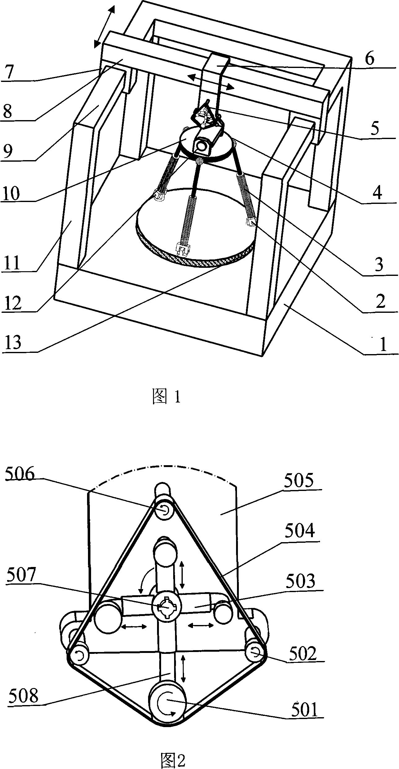
[0025] The overall structure of the present embodiment is shown in Figure 1, the base 1 and the frame 11 form a fixed platform, the longitudinal slides 9 and the transverse slides 8 are horizontally and vertically distributed and installed on the top of the frame 11, and the polishing tool system 5 passes through the horizontal Slide block 6 moves along transverse slideway 8, and transverse slideway 8 moves along longitudinal slideway 9 through longitudinal slide block 7. The lower platform 13 is fixed on the base 1, and the two ends of the three telescopic connecting rods 3 are respectively connected to the upper platform 10 and the lower platform 13 through three hinges arranged at 120°, wherein the hinges connecting the upper platform 10 are three-degree-of-freedom balls Hinge 4, the hinge that connects lower platform 13 is revolving joint 2, and the driving mode of telescoping link 3 can adopt motor and lead screw pair to drive, also can adopt servo oil cylinder to drive. ...
Embodiment 2
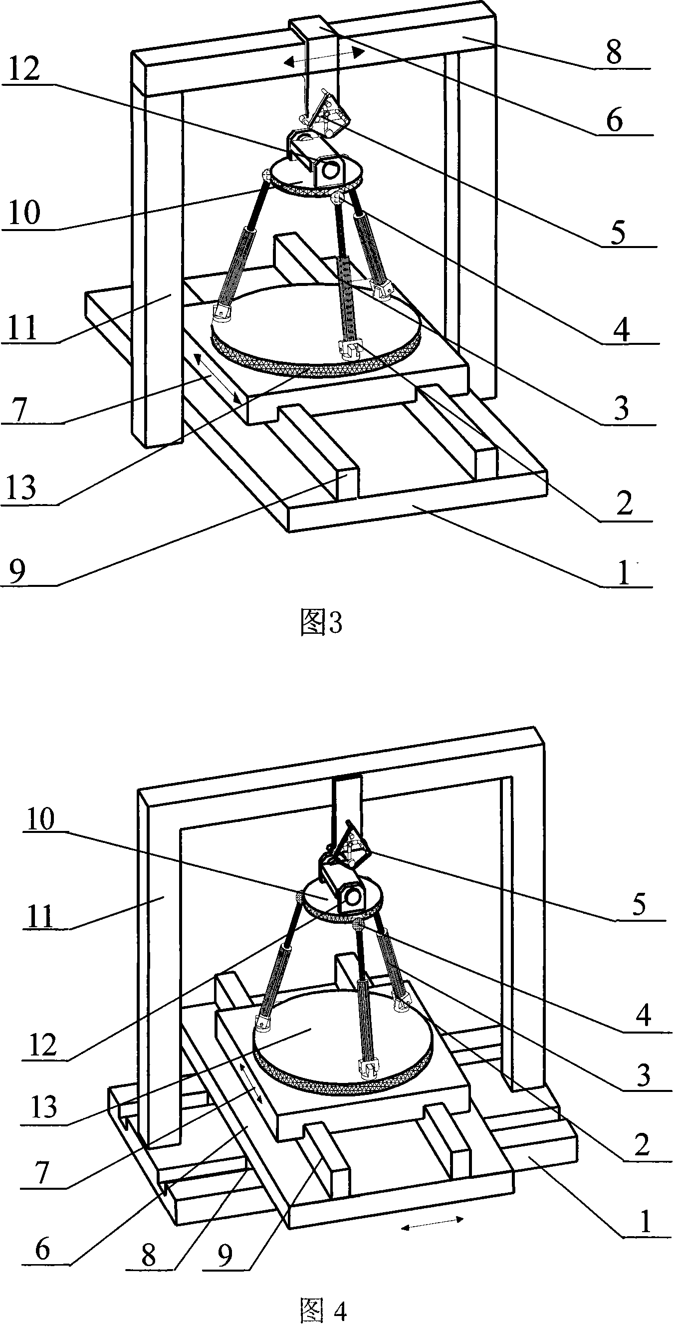
[0027] The overall structure of the present embodiment is shown in Figure 3, the base 1 and the frame 11 form a fixed platform, the longitudinal slideway 9 is installed on the base 1, the transverse slideway 8 is installed on the top of the frame 11, the longitudinal slideway 9 and the transverse slideway The roads 8 are distributed horizontally and vertically, the lower platform 13 moves along the longitudinal slideway 9 through the longitudinal slide block 7, and the polishing tool system 5 moves along the transverse slideway 8 through the transverse slide block 6. The two ends of the three telescopic connecting rods 3 are respectively connected to the upper platform 10 and the lower platform 13 through three hinges arranged at 120°, wherein the hinge connecting the upper platform 10 is a three-degree-of-freedom ball hinge 4, and the hinge connecting the lower platform 13 For the revolving pair 2, the driving mode of the telescopic connecting rod 3 can be driven by a motor an...
Embodiment 3
[0029]The overall structure of this embodiment is shown in Figure 4, the base 1 and the frame 11 form a fixed platform, and the longitudinal slides 9 and horizontal slides 8 distributed horizontally and vertically are superimposed and installed on the base 1 to form an upper and a lower slide. , the lower platform 13 moves along the longitudinal slideway 9 through the longitudinal slide block 7, and the longitudinal slideway 9 moves along the transverse slideway 8 through the transverse slide block 6, and the polishing tool system 5 is fixed on the top of the frame 11. The two ends of the three telescopic connecting rods 3 are respectively connected to the upper platform 10 and the lower platform 13 through three hinges arranged at 120°, wherein the hinge connecting the upper platform 10 is a three-degree-of-freedom ball hinge 4, and the hinge connecting the lower platform 13 For the revolving pair 2, the driving mode of the telescopic connecting rod 3 can be driven by a motor ...
PUM
 Abstract
Description
Claims
Application Information
 - R&D
- Intellectual Property
- Life Sciences
- Materials
- Tech Scout
- Unparalleled Data Quality
- Higher Quality Content
- 60% Fewer Hallucinations
Browse by: Latest US Patents, China's latest patents, Technical Efficacy Thesaurus, Application Domain, Technology Topic, Popular Technical Reports.
© 2025 PatSnap. All rights reserved.Legal|Privacy policy|Modern Slavery Act Transparency Statement|Sitemap|About US| Contact US: help@patsnap.com


