
A knife edge polishing device with circular arc

A scalpel and surgical blade technology, which is applied in the direction of grinding machines, grinding workpiece supports, grinding/polishing equipment, etc., can solve the problems of reducing processing progress, unsatisfactory results, and worn out blades, and achieve the effect of improving work efficiency

Active Publication Date: 2018-05-11
STERILANCE MEDICAL SUZHOU
View PDF9 Cites 0 Cited by
  • Summary
  • Abstract
  • Description
  • Claims
  • Application Information

AI Technical Summary

Problems solved by technology

[0003] However, due to the complex processing of the blade with the arc scalpel blade, there are the following disadvantages in manual polishing: first, manual polishing relies on manual operation experience, and the polishing of the blade must be done by skilled operators. The effect of polishing by novice operators may not be ideal, and may even damage the blade; second, there is a safety hazard for the operator to perform polishing by holding the blade; third, the efficiency of manual polishing is low
However, the blade needs to be turned over and transported during the two clampings. This process is time-consuming and labor-intensive, and also reduces the processing progress.

Method used


Image

  • A knife edge polishing device with circular arc
  • A knife edge polishing device with circular arc
  • A knife edge polishing device with circular arc

Examples


Embodiment 1

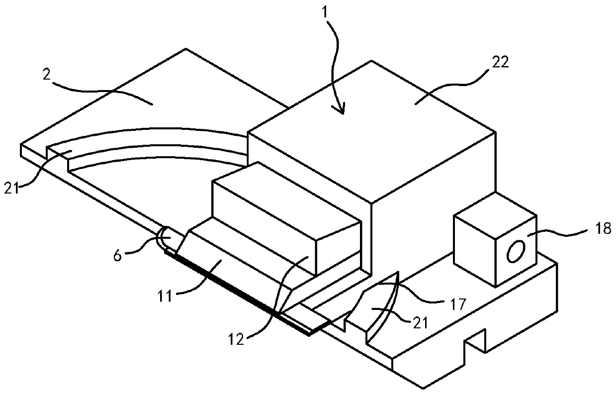
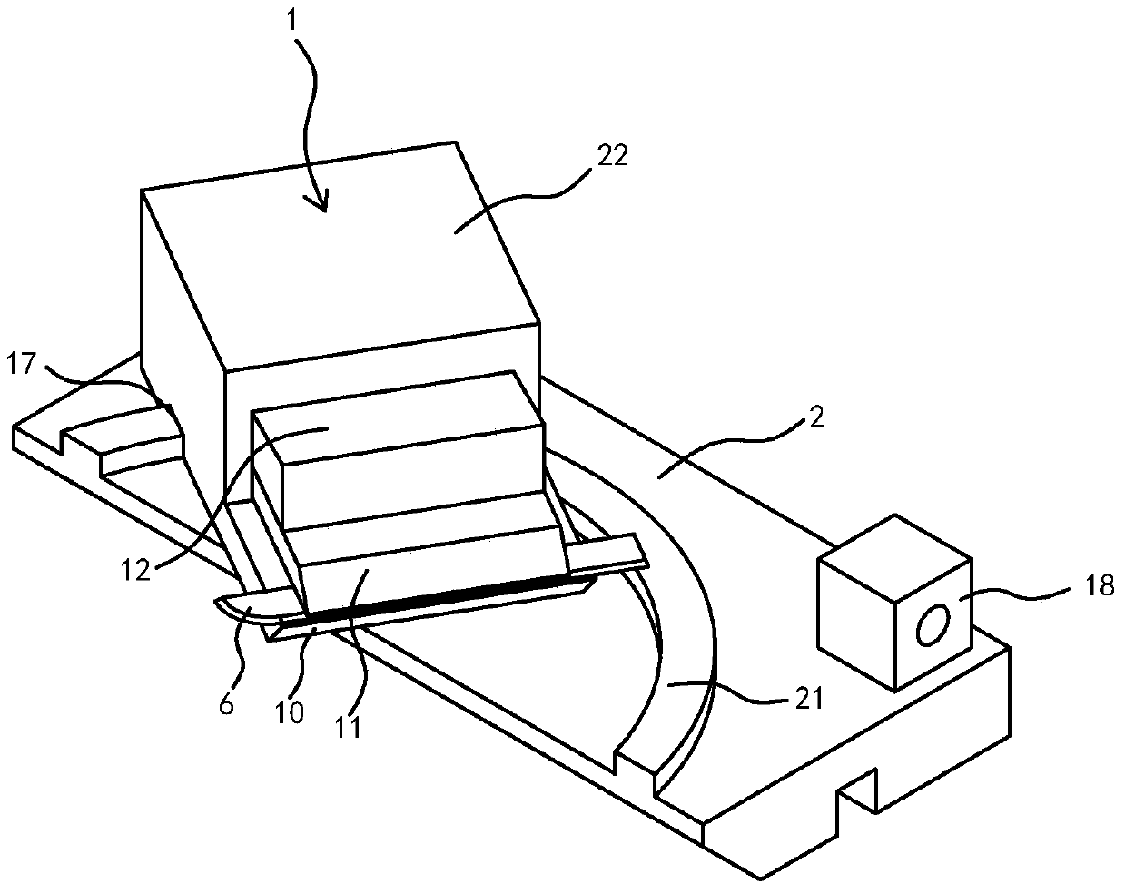
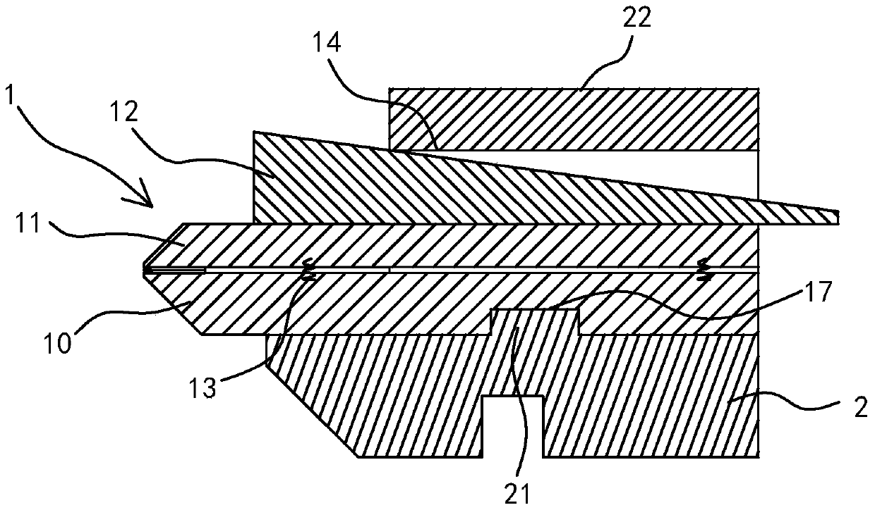
[0066] Embodiment one: see attached Figure 1-4 , attached Figure 10 , specifically a polishing device for a scalpel with a circular arc, including a machine base 5 and two groups of polishing fixtures and two groups of polishing head mechanisms arranged on the machine base 5 .

[0067] Such as Figure 1-2 As shown, the polishing fixture includes a tool holder 1 and a track bottom plate 2 . The knife holder 1 has a clamping mechanism for clamping the surgical blade 6, and the clamping mechanism has two states of clamping and loosening. When in the clamping state, the knife holder 1 clamps the surgical blade 6 in the knife holder 1 , and when in the relaxed state, the knife holder 1 releases the surgical blade 6 .

[0068] The tool holder 1 is placed on the track bottom plate 2 , and an arc track 21 and a matching body 17 matching the arc track 21 are arranged between the track bottom plate 2 and the tool holder 1 . In this embodiment, the arc track 21 is located on the tr...


PUM


Abstract

The invention relates to a knife edge polishing and grinding device provided with an arc-shaped scalpel. The knife edge polishing and grinding device comprises a base, a polishing and grinding fixture and a polishing and grinding head mechanism; the polishing and grinding fixture comprises a knife clamping base and a rail base plate, an arc-shaped rail and a matching body are arranged between the knife clamping base and the rail base plate, and a swing mechanism is formed by the knife clamping base and the rail base plate by matching of the arc-shaped rail and the matching body; when external force is acted on the knife clamping base, the knife clamping base swings on the rail base plate along the arc-shaped rail. A prismatic pair is arranged between the polishing and grinding fixture and the base or between the polishing and grinding head mechanism and the base, so that relative motion is generated between the polishing and grinding fixture and the polishing and grinding head mechanism; the polishing and grinding head mechanism comprises a first polishing and grinding wheel and a second polishing and grinding wheel, and the first polishing and grinding wheel and the second polishing and grinding wheel are arranged in a staggered mode in the direction of the relative motion of the polishing and grinding fixture and the polishing and grinding head mechanism. According to the knife edge polishing and grinding device, the structure is simple, the conception is ingenious, the cost is low, and the work efficiency is high. By means of the simple structure, effective space avoidance is achieved, therefore double-faced polishing and grinding can be carried out on a scalpel blade, and the processing efficiency of the knife edge polishing and grinding device is improved in multiples.

Description

technical field [0001] The invention belongs to production equipment for surgical blades, in particular to a polishing device for a surgical knife edge, in particular to a polishing device suitable for a circular arc surgical knife edge. The scalpel blade polishing device refers to a blade polishing device, a blade grinding device or a blade grinding and polishing device. Corresponding to the blade polishing device, the polishing wheel is the polishing wheel (the polishing wheel can be a nylon wheel, a cloth wheel, a wool wheel or a leather wheel, etc.), and corresponding to the blade grinding device, the polishing wheel is a grinding wheel (the grinding wheel can be a resin grinding wheel, Ceramic grinding wheel, etc.), corresponding to the blade grinding and polishing device, the polishing wheel must have both a grinding wheel and a polishing wheel. Background technique [0002] The production of surgical blades in China has a history of more than 50 years. Among them, th...

Claims


Application Information

Patent Timeline
Patent Type & Authority Patents(China)
IPC IPC(8): B24B3/36B24B41/06B24B3/00B24B27/00
CPCB24B3/00B24B3/36B24B27/0076B24B41/06
Inventor 施迎敢
Owner STERILANCE MEDICAL SUZHOU
Learn More