Quick-speed synchronization parallelly-arranged system between electric networks and method of use thereof

A power grid and fast technology, applied in the field of synchronous parallel and ring network parallel systems, can solve the problems of low automation level, slow synchronous parallel speed, accident expansion, etc., and achieve the effect of increasing automation, improving safety and reliability, and preventing accident expansion

Inactive Publication Date: 2008-03-12
贺长宏
View PDF0 Cites 5 Cited by
  • Summary
  • Abstract
  • Description
  • Claims
  • Application Information

AI Technical Summary

Problems solved by technology

[0012] Sometimes, in order to restore the connection of the system as soon as possible and eliminate the fault state, it is necessary to force the manual quasi-synchronous paralleling when the frequency difference and voltage difference are large, and the speed when the slip crosses the zero point is fast. A large system impact, in serious cases, will cause the relay protection device to act on tripping, causing the parallel failure and expanding the accident
[0013] Second, during the parallel operation of the long line ring network, although the pressure difference on both sides of the parallel point is small and the frequency difference is zero, due to the influence of the power flow, there will be a large phase angle difference
[0015] 1. The parallel speed is slow in the same period
Especially in the event of an accident, it is extremely unfavorable to quickly eliminate system oscillation, prevent the expansion of the accident, quickly restore the normal operation of the power grid, and ensure the safe operation of the system if it cannot quickly provide rapid active support to the low-cycle power grid.
In severe cases, part of the load of the low-cycle power grid should be cut off, r

Method used


Image

  • Quick-speed synchronization parallelly-arranged system between electric networks and method of use thereof
  • Quick-speed synchronization parallelly-arranged system between electric networks and method of use thereof
  • Quick-speed synchronization parallelly-arranged system between electric networks and method of use thereof

Examples


Embodiment Construction

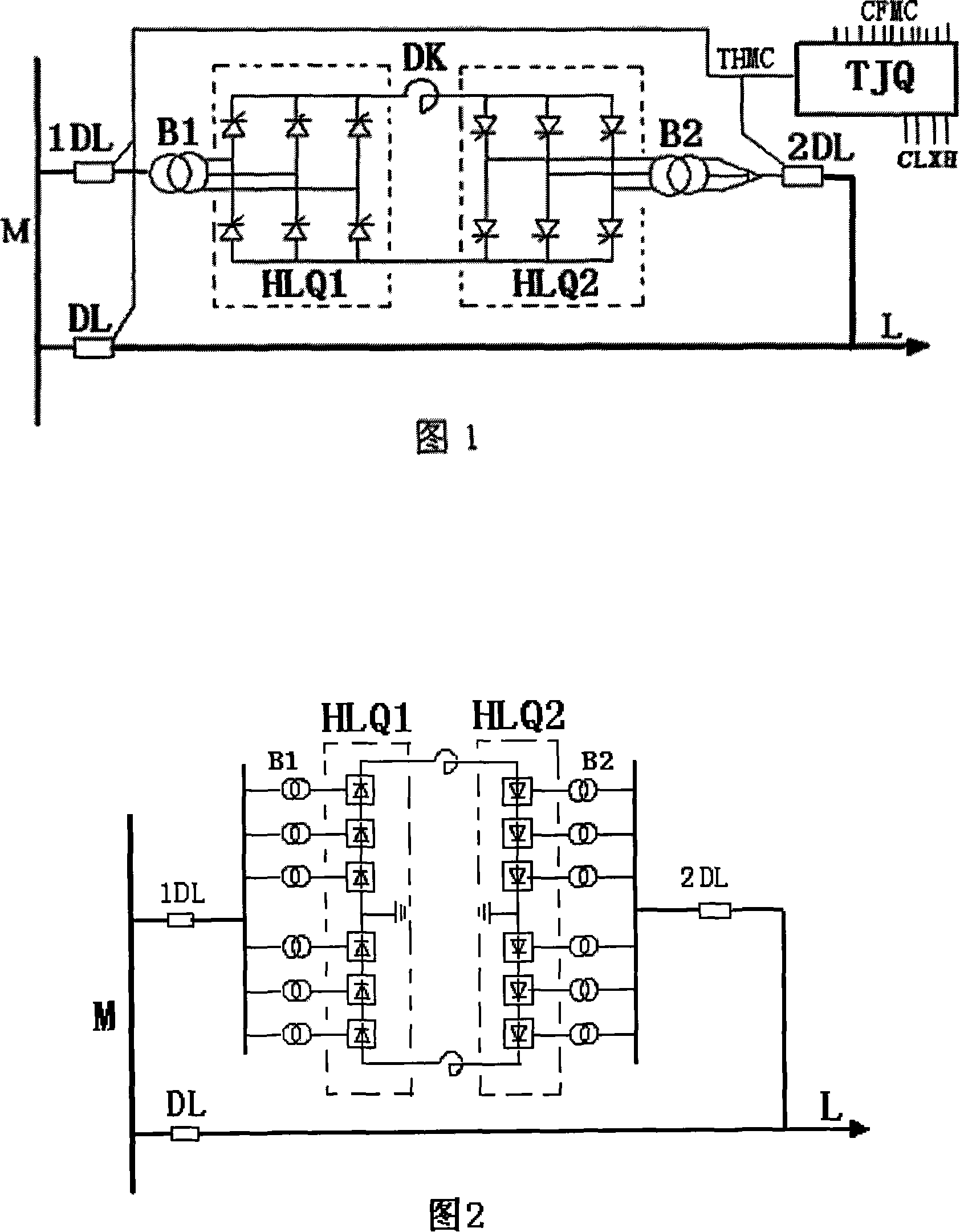
[0053] Figure 1 is a schematic diagram of the first type of parallel system composed of converters composed of thyristors. In the figure, two switches 1DL and 2DL, two converter transformers B1 and B2, two sets of thyristor converters HLQ1 and HLQ2, a set of smoothing reactor DK and control regulator TJQ constitute a thyristor parallel system . The DC side of the two groups of converters and the flat wave reactance are electrically connected end to end to form a circular closed loop. The AC side of the first group of converters HLQ1 is connected to the bus M through the converter transformer B1 and the switch 1DL. The second group of converters HLQ2 The AC side of the circuit is connected to the line L through the converter transformer B2 and the switch 2DL, and the whole parallel system works under the control and regulation of the control regulator TJQ.

[0054] The switches 1DL and 2DL on both sides of the parallel system are high-voltage circuit breakers. In actual use, o...


PUM


Abstract

The invention provides a quick corresponding parallel system between electric networks and a relative application method, which relates to a rectifying-investing system formed by high voltage electric power electric appliances, and can quickly connect two electric networks with different frequencies, quickly realize load support from the circle electric network to the low circle electric network, and eliminate the system vibration to prevent accident expansion. Following the load transmission, after satisfying the conditions of corresponding parallel, the two networks automatically complete the corresponding parallel, and exit the quick parallel system; besides, the same method also can quickly achieve ring network parallel operation for the line. Being safe and reliable, the invention has advantages of quick parallel speed and high automatization level, thereby radically solving the situation of manual operation in the prior electric network parallel; moreover, the parallel system is further applicable to the test of rising current and rising voltage for the line.

Description

Technical field [0001] The invention relates to a synchronous parallel and ring network parallel system between power grids, in particular to a high-voltage power electronic device (SCR, gate turn-off thyristor GTO, insulated gate bipolar transistor IGBT, integrated gate commutation Thyristor IGCT) composed of rectification - inverter system. Background technique [0002] At present, large-scale hub substations play a very important role in connecting inter-provincial power grids, regional power grids and international power grids. The rapidity and safety of the parallel operation in the hub substation is related to whether the system can quickly restore the system in the event of an accident, and whether it can provide active support to the low-cycle power grid in time to eliminate system oscillation, prevent the expansion of the accident, and ensure the user’s Continuous power supply or fast restoration of power supply. However, there are the following problems in the sy...

Claims


Application Information

Patent Timeline
IPC IPC(8): H02J3/38
Inventor 贺长宏
Owner 贺长宏
Why Eureka
Try Eureka