
Optimized multi-carrier signal slicing device and method therefor

A multi-carrier signal and multi-carrier technology, applied in multi-frequency code systems and other directions, can solve the problems of high signal processing pressure, complex implementation structure, spectrum diffusion effect, etc., to reduce costs, improve output efficiency, and realize hardware structure. simple effect

Inactive Publication Date: 2010-04-21
ZTE CORP
View PDF2 Cites 0 Cited by
  • Summary
  • Abstract
  • Description
  • Claims
  • Application Information

AI Technical Summary

Problems solved by technology

Although the patent performs clipping processing for different carrier powers, which can have a small impact on the EVM of the weaker carrier signal, this processing structure usually requires two clipping processings to obtain a more ideal peak-to-average ratio index , the structure of this scheme is relatively complex, and requires more hardware resources to obtain a better clipping effect. At the same time, the method of hard clipping will cause serious spectrum diffusion effects. In this way, the premise of meeting a certain linearity index The processing of the clipped signal (filter design) brings greater pressure

Method used


Image

  • Optimized multi-carrier signal slicing device and method therefor
  • Optimized multi-carrier signal slicing device and method therefor
  • Optimized multi-carrier signal slicing device and method therefor

Examples


Embodiment Construction

[0065] The present invention will be described in detail below in conjunction with the accompanying drawings and specific embodiments of the present invention applied in a WCDMA multi-carrier system.

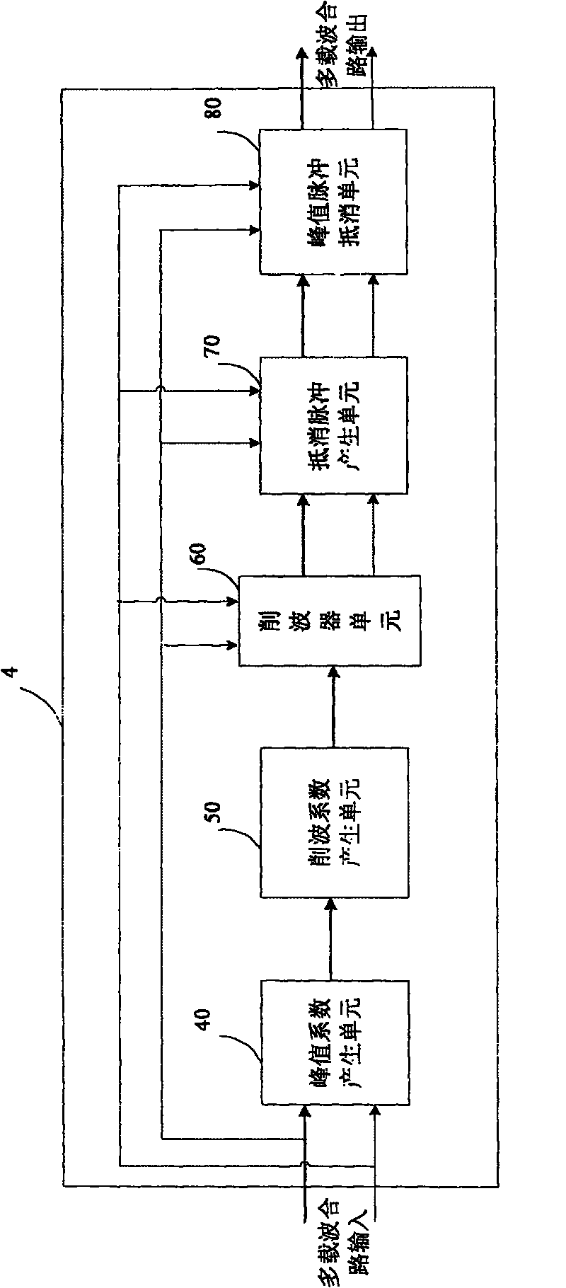
[0066] see figure 1 As shown in , it is a schematic diagram of the location of an optimized multi-carrier clipping device in the WCDMA system of the present invention.

[0067] The optimized multi-carrier clipping device can be realized by the baseband part in the system, and can also be located in the power amplifier system. Usually, when the baseband is implemented, the baseband provides subcarrier input signals, and corresponding modules (such as carrier synthesis modules) can be easily added in the digital domain to combine the subcarrier input signals into multi-carrier combined signals. If the device is located in a power amplifier system, and the input signal of the power amplifier is a radio frequency signal, the required intermediate frequency multi-carrier combination...


PUM


Abstract

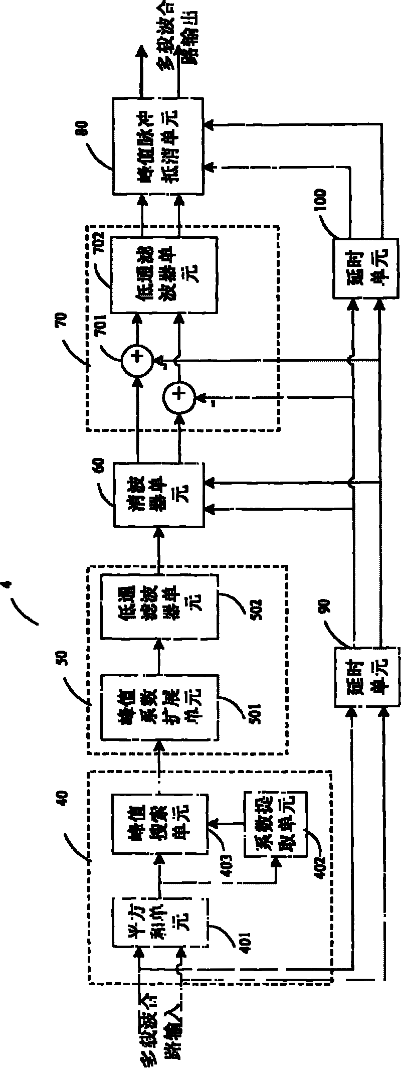
The device includes following units: peak coefficient generation unit in use for picking-up peak pulse from the input signal in multicarrier joined route (ISMJR) in order to obtain peak coefficient factor (PCF) corresponding to peak pulse; clipping coefficient (CC) generation unit in use for processing PCF to obtain CC corresponding to peak pulse; being connected to CC generation unit, clipper unit in use for carrying out weighting process based on CC for time-delay processed ISMJR so as to form clipping signal; being connected to the clipper unit, cancellation pulse generation unit (CPGU) inuse for processing ISMJR and the clipping signal to form signal of cancellation pulse; being connected to CPGU, peak pulse cancellation unit in use for synthesizing time-delay processed clipping signaland signal of cancellation pulse so as to generate clipped output signal in multicarrier joined route. The invention saves resources and raises output efficiency of power amplification.

Description

technical field [0001] The invention relates to a signal processing device and method in the field of digital mobile communication, in particular to a multi-carrier signal clipping device and method for reducing the signal peak-to-average ratio of a multi-carrier communication system. Background technique [0002] At present, the wireless communication system adopts BPSK (Binary Phase Shift Key, binary phase shift keying), QPSK (Quadrature Phase Shift Key, quadrature phase shift keying), 8QAM (8Quadrature Amplitude Modulation, 8 quadrature phase shift keying) Amplitude modulation), 16QAM (16QuadratureAmplitude Modulation, 16 quadrature amplitude modulation) and other modulation methods, these modulation methods not only modulate the phase of the carrier, but also modulate the amplitude of the carrier, these modulation methods will produce a large peak-to-average ratio. Envelope modulation signals, these signals with a large peak-to-average ratio will cause some semiconductor...

Claims


Application Information

Patent Timeline
Patent Type & Authority Patents(China)
IPC IPC(8): H04L27/26
Inventor 邓英茹洪涛孙波
Owner ZTE CORP
Learn More