Storage device for liquefied gas fuel
A storage device and liquefied gas technology, applied in the direction of liquid fuel feeder, oil supply device, power device, etc., can solve the problems of increased weight, equal storage capacity of liquefied gas fuel, and increased cost
- Summary
- Abstract
- Description
- Claims
- Application Information
AI Technical Summary
Problems solved by technology
Method used
Image
Examples
Embodiment 1
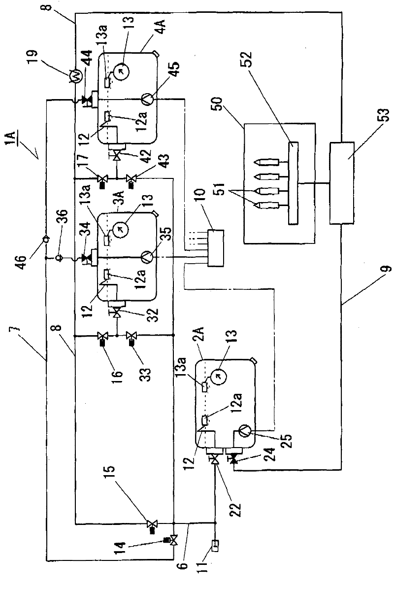
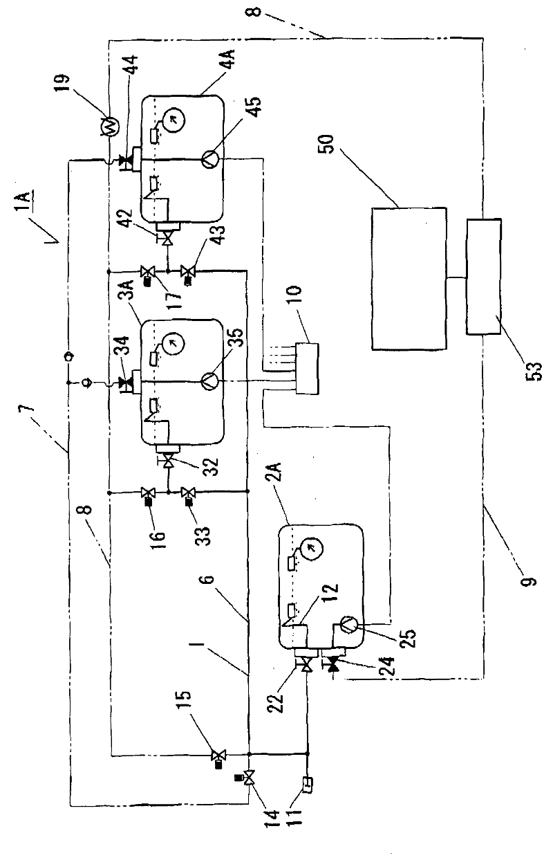
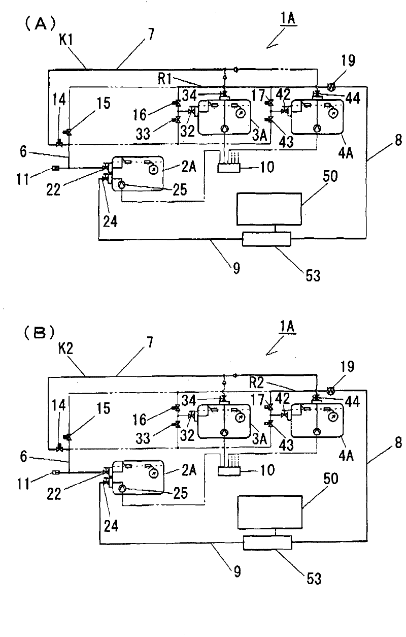
[0064] The liquefied gas fuel storage device 1A of this embodiment is mounted on an automobile and stores liquefied gas fuel as fuel for the engine 50 thereof. figure 1 It is a conceptual diagram of a storage device 1A for liquefied gas fuel, and includes a first storage tank 2A and two second storage tanks 3A and 4A, making a total of three storage tanks.
[0065] In the liquefied gas fuel storage device 1A, a quick joint 11 that can be detached from a filling gun (not shown) that injects liquefied gas fuel from the outside is installed. Filling pipe 6 of the second storage tank 3A, 4A. Here, the filling pipe 6 is branched to communicate with the filling valve 22 disposed on the first storage tank 2A, the filling valve 32 disposed on the second storage tank 3A, and the filling valve 42 disposed on the second storage tank 4A. connect. Furthermore, at positions immediately upstream of the filling valves 32 and 42 of the second storage tanks 3A and 4A in the filling pipe 6 , s...
Embodiment 2
[0090] In the liquefied gas fuel storage device 1B of embodiment 2, such as Figure 4 As shown, there are two second storage tanks 3B, 4B, and heaters 61, 62 are provided at the lower positions inside the respective tanks. Then, in the second storage tanks 3B, 4B, the suction pipes 63 , 64 communicating with the supply pipe 7 via the respective supply take-out valves 34 , 44 are respectively disposed therein. Here, the lower ends of the respective suction pipes 63 and 64 are provided at positions close to the bottom of the tank. That is, the positions of the lower ends of the suction pipes 63 and 64 become the lower limits of the second storage tanks 3B and 4B where the liquefied gas fuel can be supplied.
[0091] In addition, in the second embodiment, as in the first embodiment, a control processing device 10 for controlling the operation of each pump or valve is provided, and the above-mentioned heaters 61 and 62 are controlled by the control processing device 10 . The con...
Embodiment 3
[0097] In the liquefied gas fuel storage device 1C of the third embodiment, the second storage tanks 3C, 4C with the heaters 61, 62 removed from the structure of the above-mentioned embodiment 2 are installed, and at the same time, the cooling of the fuel is controlled by the control processing device 10. The device 19 operates to cool the high-temperature liquefied gas fuel returned by the engine 50 to a specified temperature range. This composition is as Figure 5 As shown, the supply pumps 35 and 45 of the first embodiment and the heaters 61 and 62 of the second embodiment are not equipped.
[0098] Here, as the operation control of the fuel cooler 19 performed by the control processing device 10, the remaining liquefied gas fuel flows to the second storage tanks 3C, 4C in a predetermined temperature range, so that the second storage tanks 3C, 4C The temperature of the liquefied gas fuel in 4C is higher than that in the first storage tank 2A. That is, as in the above-ment...
PUM
 Abstract
Description
Claims
Application Information
 - Generate Ideas
- Intellectual Property
- Life Sciences
- Materials
- Tech Scout
- Unparalleled Data Quality
- Higher Quality Content
- 60% Fewer Hallucinations
Browse by: Latest US Patents, China's latest patents, Technical Efficacy Thesaurus, Application Domain, Technology Topic, Popular Technical Reports.
© 2025 PatSnap. All rights reserved.Legal|Privacy policy|Modern Slavery Act Transparency Statement|Sitemap|About US| Contact US: help@patsnap.com


