Picture processing engine and picture processing system
An image processing and engine technology, applied in the direction of image data processing, image data processing, architecture with multiple processing units, etc., can solve problems such as large area cost, large power consumption, and increased power consumption
- Summary
- Abstract
- Description
- Claims
- Application Information
AI Technical Summary
Problems solved by technology
Method used
Image
Examples
Embodiment 1
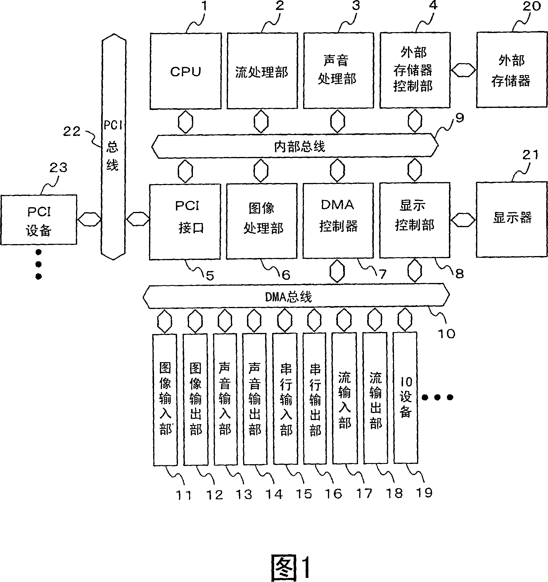
[0049] The first embodiment of the present invention will be described in detail with reference to the drawings. FIG. 1 is a block diagram of the embedded system of this embodiment. This embedded system connects the following parts to each other on the internal bus 9: CPU1, which performs system control and general processing; stream processing unit 2, which performs one processing of MPEG and other image codecs, that is, stream processing; image processing unit 6. Cooperate with the stream processing unit 2 to encode and decode the image codec; the audio processing unit 3 to encode and decode audio codecs such as AAC or MP-3; the external memory control unit 4, which is controlled by SDRAM, etc. Access to the constituted external memory 20; PCI interface 5, used to connect to the standard bus, namely PCI bus 22; display control unit 8, to control image display; and DMA controller 7, to perform direct memory access to various IO devices.
[0050] Various IO devices are connected t...
Embodiment 2
[0149] The second embodiment of the present invention will be explained with reference to FIG. 14. FIG. 14 is a block diagram of the image processing unit 66 of this embodiment. Compared with the image processing engine 66 of the first embodiment shown in FIG. 6, there are three differences. The first point is that the input data 30i and calculation data 30wb of the CPU unit 30 are connected to the vector calculation unit 46. The input data 30i is data to be input to the register file 304 in the CPU unit 30, and the data of the register file 304 can be updated. The calculation data 30wb is the calculation result of the CPU unit 30 and is input to the vector calculation unit 46. In the second place, a command memory control unit 47 is connected instead of the command memory control unit 32 in FIG. 6. The command memory control unit 47 has a plurality of program counters and controls the command memory 31. In addition, the third difference is that the vector calculation unit 46 is c...
Embodiment 3
[0169] The third embodiment will be explained with reference to FIG. 20. FIG. 20 is a configuration diagram of a CPU section arranged in the image processing engine 66 of this embodiment. In the first embodiment, it is constituted by one CPU unit 30; in the second embodiment, it has been described that it is constituted by two CPUs, the CPU unit 30 and the vector operation unit 46. In the third embodiment, two or more CPUs are connected in series or in a ring. In FIG. 3, a CPU unit 30 that can access the data memory 35 is arranged on the first CPU, a plurality of vector operation units 46 and 46n are connected in series, and a CPU unit 30s that can access the data memory 35 is connected to the end. The calculation data 30i of the CPU section 30s is connected to the input data section of the CPU section 30 again. At this time, each CPU has a structure having a program counter, and actually has a structure having a plurality of program counters in the instruction memory control unit...
PUM
 Abstract
Description
Claims
Application Information
 - R&D Engineer
- R&D Manager
- IP Professional
- Industry Leading Data Capabilities
- Powerful AI technology
- Patent DNA Extraction
Browse by: Latest US Patents, China's latest patents, Technical Efficacy Thesaurus, Application Domain, Technology Topic, Popular Technical Reports.
© 2024 PatSnap. All rights reserved.Legal|Privacy policy|Modern Slavery Act Transparency Statement|Sitemap|About US| Contact US: help@patsnap.com


