
Self-power-supply magnetorheological intelligent vibration damping device

A technology of intelligent vibration reduction and magnetorheological damper, which is applied in vibration suppression adjustment, non-rotational vibration suppression, building components, etc., can solve the problems of large environmental interference, small induced electromotive force, and high cost, and achieve simplified semi-active damping Vibration system, system cost reduction, obvious self-adaptive features

Inactive Publication Date: 2007-12-12
HUNAN UNIV
View PDF0 Cites 51 Cited by
  • Summary
  • Abstract
  • Description
  • Claims
  • Application Information

AI Technical Summary

Problems solved by technology

Existing semi-active suspension systems based on magnetorheological dampers mostly use displacement, velocity or acceleration sensors configured in parallel with magnetorheological dampers to measure the dynamic vibration information of the controlled object, which has high cost, complex structure and Environmental interference and other problems
At present, there are magneto-rheological dampers with integrated relative speed sensing functions, but the system is still too complex, including many modules such as double-coil MR dampers, signal preprocessing circuits, controllers, and current drivers.
In 2005, foreign scholars proposed to fix the permanent magnet on the piston rod of the traditional magnetorheological damper, and fix the induction coil on the outer cylinder. When the structural vibration drives the piston rod to vibrate, the magnetic flux of the induction coil changes to generate an induced electromotive force, and then Directly supply power to the excitation coil of the MR damper to implement adaptive control, but for civil engineering structures with small vibration amplitude and low frequency, the induced electromotive force generated by the induction coil is often small, coupled with circuit loss, it is difficult to put into practice Semi-Active Control Applications

Method used


Image

  • Self-power-supply magnetorheological intelligent vibration damping device

Examples


Embodiment Construction

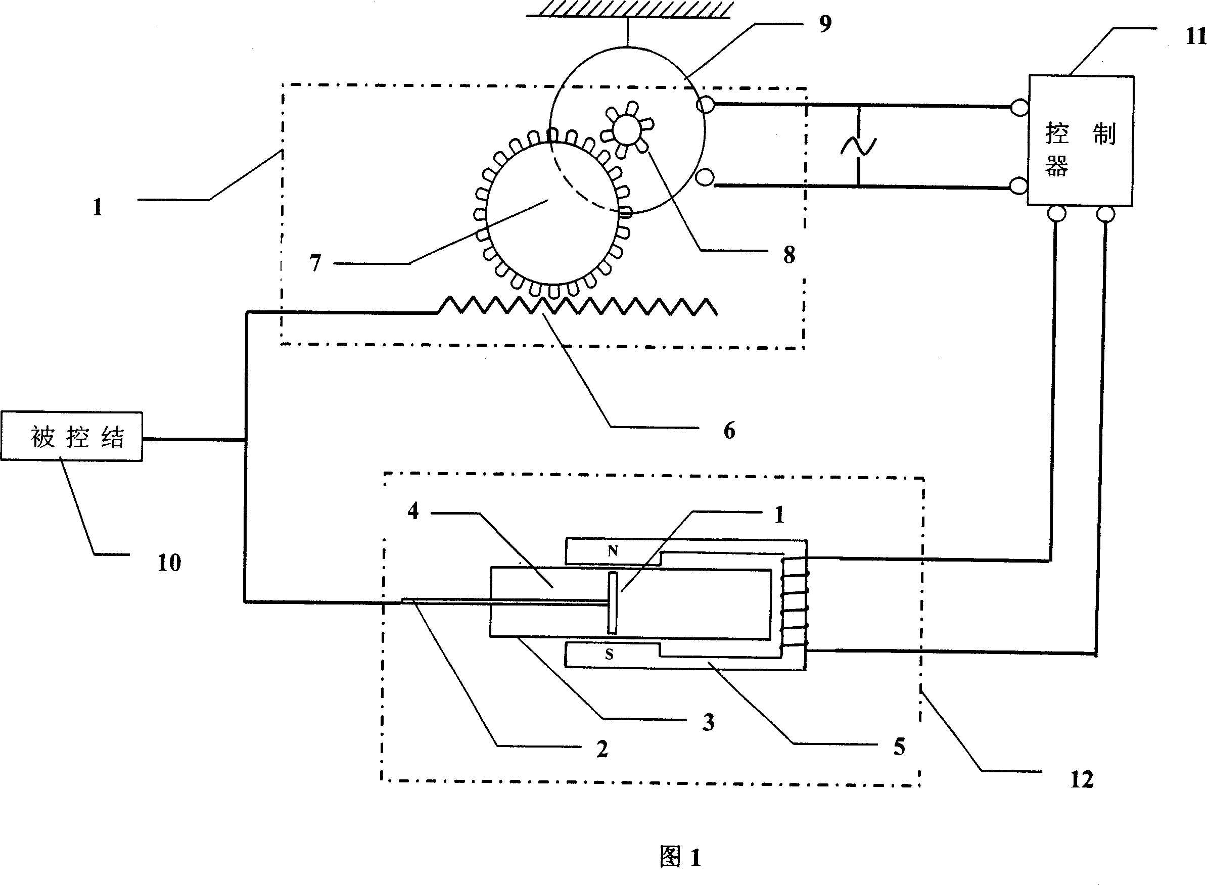
[0024] As shown in Figure 1, the self-supplied electromagnetic rheological intelligent damping system of the present invention is mainly composed of an electromagnetically adjustable magnetorheological damper 12, a rack and pinion accelerator 13, a permanent magnet DC motor 9, and a controller 11; wherein, the The piston rod 2 of the electromagnetically adjustable magneto-rheological damper 12 is fixedly connected to the rack 6 of the rack-and-pinion accelerator 13, and the final pinion of the rack-and-pinion accelerator 13 is installed on the permanent magnet DC generator On the shaft of 9, a controller 11 is installed between the output end of the permanent magnet DC generator 9 and the electromagnetic coil terminal of the electromagnetically adjustable magnetorheological damper 12, and the rack and pinion accelerator 13 and the permanent magnet DC generator 9 is integrated into one.

[0025] Described controller 11 adopts prior art, such as using a single-chip microcomputer...


PUM


Abstract

A self-power magnetic current changing intelligent vibration damping system consists of electromagnetic adjustable magnetic current changing damper, rack gear accelerator and permanent magnet DC generator, the piston rod of said damper is fixed and connected with the racks of accelerator, and the final pinion of accelerator is installed on said DC generator axle, the outlet end of the DC generator is connected with the electromagnetic coil receiving terminal of said damper, and controller is installed between the outlet end of said DC generator and the electromagnetic coil receiving terminal of the damper. The kernel technology of the invention is: it integrates the sensor of structure vibration and the power-supply source of magnetic current changing damper on small-sized permanent magnet DC generator. The invention applies to the vibration damping of civil engineering structure, it can realize semi-active real-time control without extraneous power source, reduce the system cost, and it is reliable, stable, simple and practical and has obvious self-adaptive characteristics.

Description

technical field [0001] The invention relates to a self-supplied electromagnetic rheological intelligent vibration damping system, which is suitable for semi-active control of vibration damping of civil engineering structures. Background technique [0002] Vibration control of civil engineering structures can effectively reduce the response and damage accumulation of the structure under the dynamic effects of wind, earthquake, vehicles, etc., and effectively improve the anti-vibration ability and disaster resistance performance of the structure. methods and techniques. [0003] Structural vibration control can be divided into passive control, active control, semi-active control and hybrid control. Passive control does not require external energy, but relies on the interaction between structural components, structures and auxiliary systems to consume energy, so as to achieve the purpose of vibration reduction. Active control means that in the case of external energy supply, ...

Claims


Application Information

Patent Timeline
IPC IPC(8): E04B1/98F16F9/53
Inventor 陈政清
Owner HUNAN UNIV
Learn More