Light reflector and surface light source device using the same
A light reflector and light reflection technology, applied in the direction of light source, reflector, slender light source, etc., can solve the problems of color change and yellowing of light reflector, and achieve high brightness, high reflectivity and excellent surface luminescence. Effect
- Summary
- Abstract
- Description
- Claims
- Application Information
AI Technical Summary
Problems solved by technology
Method used
Image
Examples
Embodiment 1 and Embodiment 2
[0099] The materials described in Table 1 were mixed according to the compounding ratio shown in Table 2, and the obtained composition (A) was melt-kneaded at 250° C. with an extruder. Thereafter, it was extruded in a sheet form and cooled to about 60° C. with a cooling roll to obtain a base material layer (A). After heating this base material layer (A) again to 145 degreeC, it longitudinally stretched at the magnification shown in Table 2 using the peripheral speed difference of several roll groups.
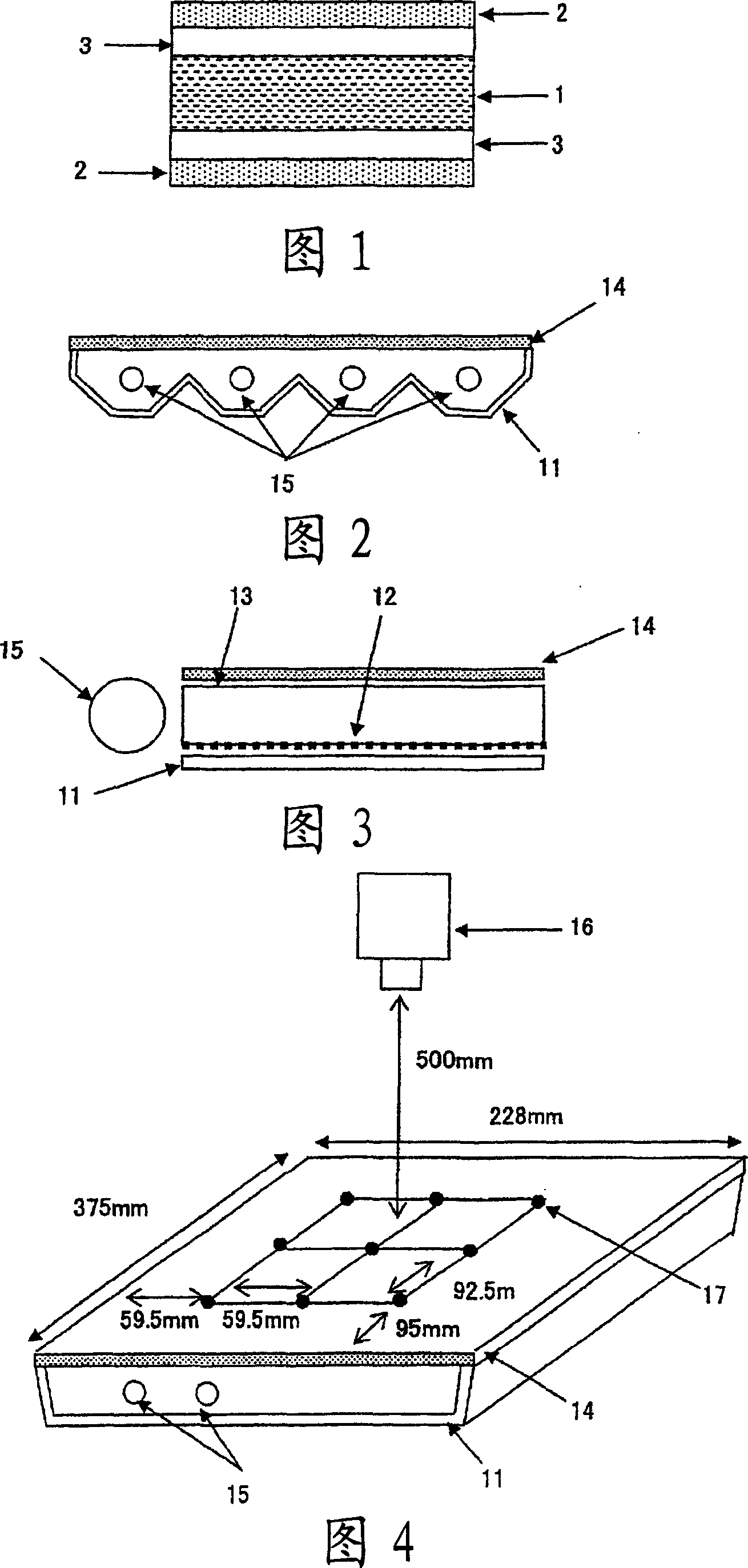
[0100] The materials described in Table 1 were mixed according to the proportions shown in Table 2, the obtained compositions (B) and (C) were melt-kneaded, and the kneaded product was melt-extruded onto the obtained substrate On both surfaces of the layer (A), the light-diffusing layer (B) and the protective layer (C) are laminated in a B / C / A / C manner. Next, this laminate was heated again to 160° C., and stretched laterally at the magnification shown in Table 2 using a tenter....
Embodiment 3
[0102] The materials described in Table 1 were mixed according to the compounding ratio shown in Table 2, and the obtained composition (A) was melt-kneaded at 250° C. with an extruder. Thereafter, it was extruded in a sheet form and cooled to about 60° C. with a cooling roll to obtain a base material layer (A). After heating this base material layer (A) again to 145 degreeC, it longitudinally stretched at the magnification shown in Table 2 using the peripheral speed difference of several roll groups.
[0103] The materials described in Table 1 were mixed according to the proportions shown in Table 2, the obtained composition (C) was melt-kneaded, and the kneaded product was melt-extruded into the obtained substrate layer (A) Laminate the protective layer (C) in the manner of C / A / C on both sides. Next, this laminate was heated again to 160° C., and stretched laterally at the magnification shown in Table 2 using a tenter. Then, softening treatment was performed at 160° C. and ...
Embodiment 4
[0105]Using a molding roll with a depth of 58 μm and a pitch of 145 μm, which is an equilateral triangle in cross section, under the conditions of 100 kg of pressure, 80° C., and a linear speed of 3 m / min, the light-reflecting surface of the substrate obtained in Example 2 was Molding is carried out to obtain a laminated film having a light-gathering function on the surface. This laminated film was used as a light reflector.
PUM
| Property | Measurement | Unit |
|---|---|---|
| particle diameter | aaaaa | aaaaa |
| particle size distribution | aaaaa | aaaaa |
| particle diameter | aaaaa | aaaaa |
Abstract
Description
Claims
Application Information
 - R&D
- Intellectual Property
- Life Sciences
- Materials
- Tech Scout
- Unparalleled Data Quality
- Higher Quality Content
- 60% Fewer Hallucinations
Browse by: Latest US Patents, China's latest patents, Technical Efficacy Thesaurus, Application Domain, Technology Topic, Popular Technical Reports.
© 2025 PatSnap. All rights reserved.Legal|Privacy policy|Modern Slavery Act Transparency Statement|Sitemap|About US| Contact US: help@patsnap.com


