
Apparatus for low-temperature plasma treatment

A low-temperature plasma and plasma technology, applied in the direction of discharge tubes, electrical components, circuits, etc., can solve problems such as insufficient vacuum, damage to the drive mechanism, and metal corrosion, so as to avoid film damage or pollution, reduce maintenance costs, and improve surface quality. Handle the effect of uniformity

Inactive Publication Date: 2007-11-28
SHIN ETSU CHEM IND CO LTD
View PDF2 Cites 3 Cited by
  • Summary
  • Abstract
  • Description
  • Claims
  • Application Information

AI Technical Summary

Problems solved by technology

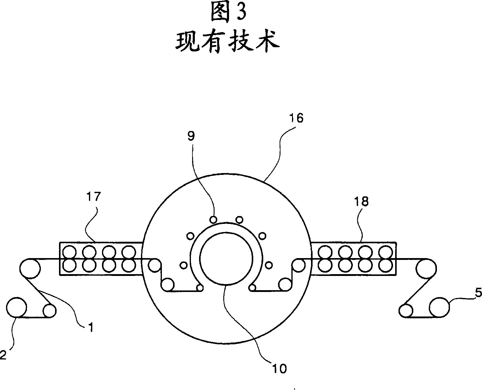
[0005] When the device uses a sealing arrangement as shown in Japanese Laid-Open Patent Application No. S57-18737, the film is fed through a series of paired sealing rollers, which enables gaps to be formed between the sealing rollers, as the sealing rollers wear and deteriorate, And other gases different from the processing gas can permeate into the device, so that the sealing is extremely difficult, and the vacuum degree in the vacuum chamber is insufficient, and there will be problems leading to insufficient low temperature plasma processing
[0006] In addition, the film is interposed between opposing seal rollers, so that a heavy load may be applied to the film at the time of unwinding due to wear or deterioration of the seal rollers, the dimensional stability of the film will deteriorate and the film may be damaged or scratched. hurt
[0007] The method of No. H09-209158 Japanese Published Patent Application is to place the unwinding unit and the winding unit in a single vacuum chamber, so that there is no problem caused by the insufficient sealing effect of the sealing drum as shown in the S57-18737 Japanese Published Patent Application, but Since the drive mechanism is placed in the same vacuum chamber, there may be problems with the drive mechanism being damaged by the plasma, or due to the corrosion of the metal by the plasma-activated gas

Method used


Image

  • Apparatus for low-temperature plasma treatment
  • Apparatus for low-temperature plasma treatment
  • Apparatus for low-temperature plasma treatment

Examples


example 1

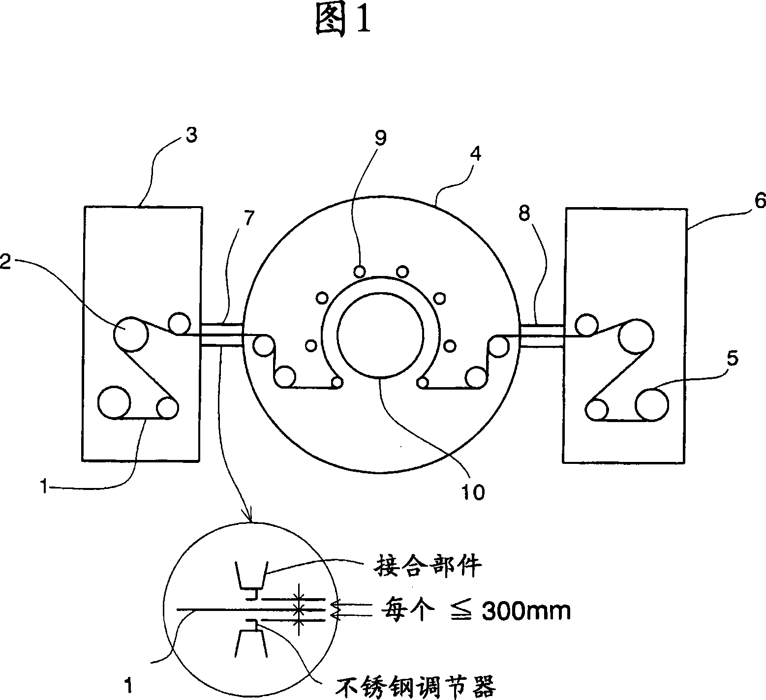
[0039] Using the device of the construction shown in Figure 1, the vacuum chamber is made of stainless steel. A 12 μm thick polyethylene terephthalate (PET) film (product name: Lumirror, manufacturer: Toray) was unwound by an unwinding unit, and run through a plasma treatment device (manufacturer: Shin-Etsu Engineering Co. .), and the winding unit runs through the slit at the junction part between the first vacuum chamber and the second vacuum chamber and the slit at the junction part between the second vacuum chamber and the third vacuum chamber with the PET film. The width of the slit was adjusted by using stainless steel shoes so as to have a gap of 290 mm each above and below the surface of the PET film.

[0040] After conditioning the PET film, the vacuum chamber was closed, and the vacuum chamber was evacuated. When the vacuum pressure reached 2 Pa, nitrogen gas was introduced into the second vacuum chamber at a rate of 1 l / min, and the pressure in each vacuum chamber w...

example 2

[0043] Using the apparatus shown in Fig. 1, low-temperature plasma treatment was carried out in the same manner as in Example 1, except that the iron vacuum chamber was sprayed with a layer of SUS304 stainless steel on its inner surface by flame spraying.

example 3

[0045] Using the device shown in Fig. 1, the low-temperature plasma treatment is carried out in the same manner as in Example 1, except that the material of the vacuum chamber is changed from stainless steel to ordinary steel, and the film used for processing is changed to a 25 μm thick PI film (product Name: Apical, Manufacturer: KanekaCo.).


PUM

PropertyMeasurementUnit
thicknessaaaaaaaaaa

Abstract

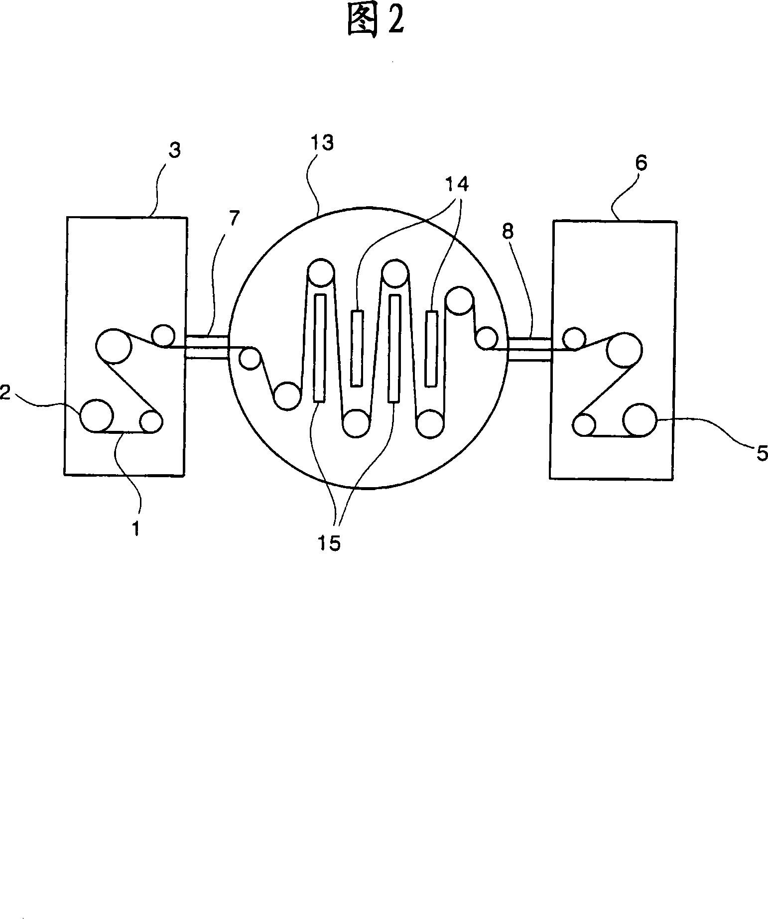
An apparatus for low-temperature plasma treatment of a continuous length plastic film which can work for surface modifying processing for a film using low-temperature plasma while maintaining the dimensional stability without causing damage to the film. The apparatus for performing surface modifying processing for a film comprises: a first vacuum chamber equipped with an unrolling unit for unrolling a rolled plastic film; a second vacuum chamber in which the unrolled plastic film is subjected to a low-temperature plasma treatment on the surface; and a third vacuum chamber equipped with a winding unit for winding the plasma-treated plastic film into a roll, the vacuum chambers being connected together in series along the running direction of the plastic film under treatment.

Description

technical field [0001] The present invention relates to a low-temperature plasma treatment device for changing the surface properties of various types of plastic films (hereinafter simply referred to as films). Background technique [0002] So far it has been known that by means of low-temperature plasma treatment of the surface of a film, the wettability of the surface can be improved, the coatability of adhesives etc. can be improved, and the adhesion between the film and the adhesive can be improved Sex can be enhanced. [0003] Typically, films are manufactured on in-line equipment and wound into rolls, so the low-temperature plasma treatment of the surface of the roll film is best performed on in-line equipment. [0004] Therefore, use the thin film surface treatment of low-temperature plasma to carry out as shown in Figure 3, the method that uses at this moment is to place plasma treatment device in the inside of vacuum container 16, and sealing roller 17,18 is set in...

Claims


Application Information

Patent Timeline
Patent Type & Authority Applications(China)
IPC IPC(8): B29C71/04
CPCH01J37/32724C08J7/123B29C2059/147B29C59/14H01J37/3277H01J37/32541
Inventor 星田繁宏铃木真二天野正
Owner SHIN ETSU CHEM IND CO LTD
Learn More