
Rotor blade for wind power equipment

A technology for wind power generation equipment and rotor blades, which is applied in wind power generator components, wind power engine monitoring, wind power generation, etc., and can solve the problems of inability to achieve direct comparability between airflow conditions and icing conditions

Inactive Publication Date: 2007-11-21
阿洛伊斯沃本
View PDF5 Cites 8 Cited by
  • Summary
  • Abstract
  • Description
  • Claims
  • Application Information

AI Technical Summary

Problems solved by technology

However, a direct comparability of airflow conditions with icing conditions cannot therefore be achieved because other airflow conditions exist on the rotor blades

Method used


Image

  • Rotor blade for wind power equipment
  • Rotor blade for wind power equipment
  • Rotor blade for wind power equipment

Examples


Embodiment Construction

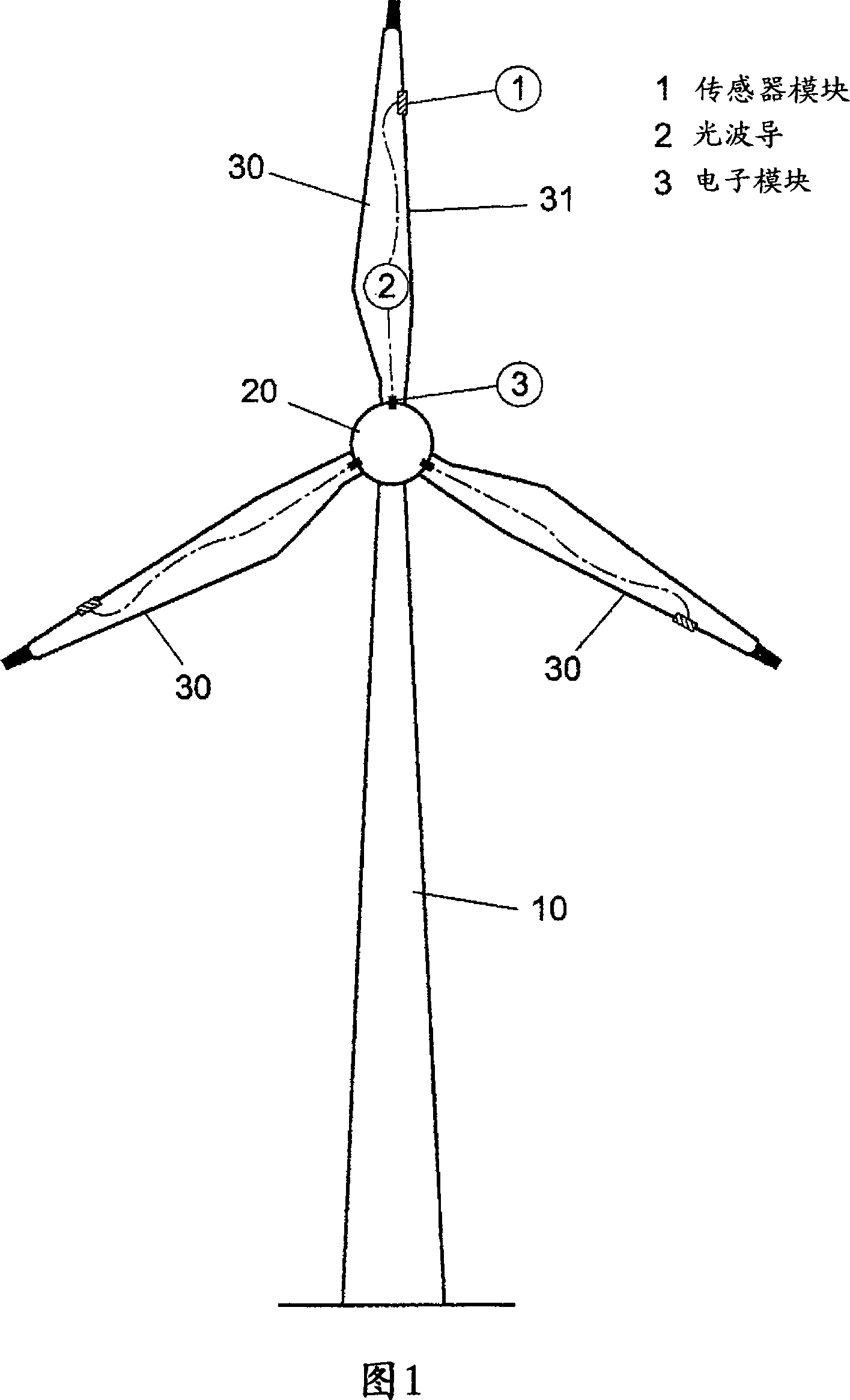
[0022] FIG. 1 shows a front view of a wind power plant according to a first embodiment. In this case, the wind power plant has a tower 10 , a nacelle 20 and three rotor blades 30 . A deposit sensor 1 is arranged on each rotor blade. Preferably, the deposit sensor 1 is arranged on the rotor blade nose. The deposit sensors 1 are respectively connected to a comparison device 3 via an optical waveguide 2 .

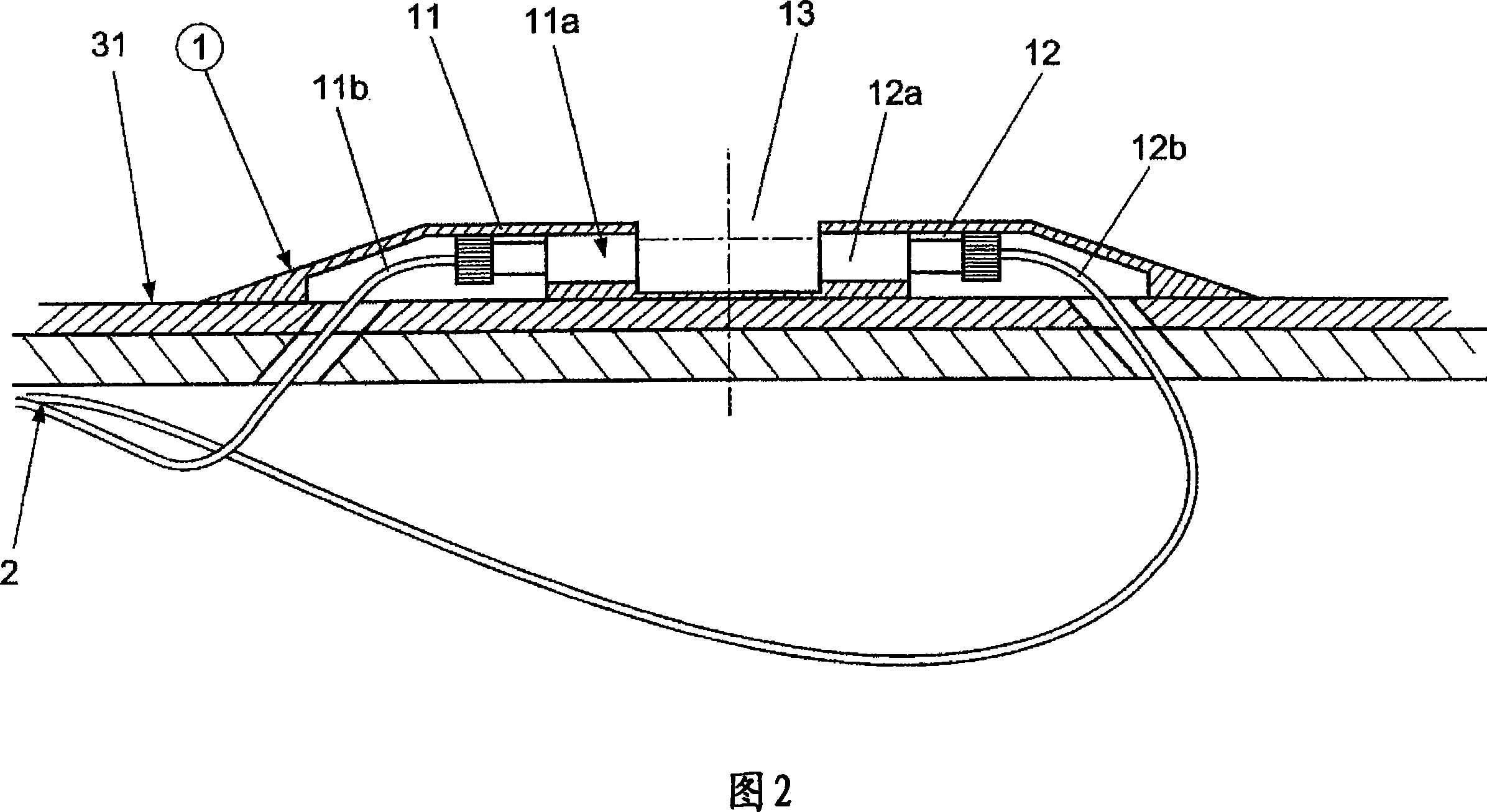
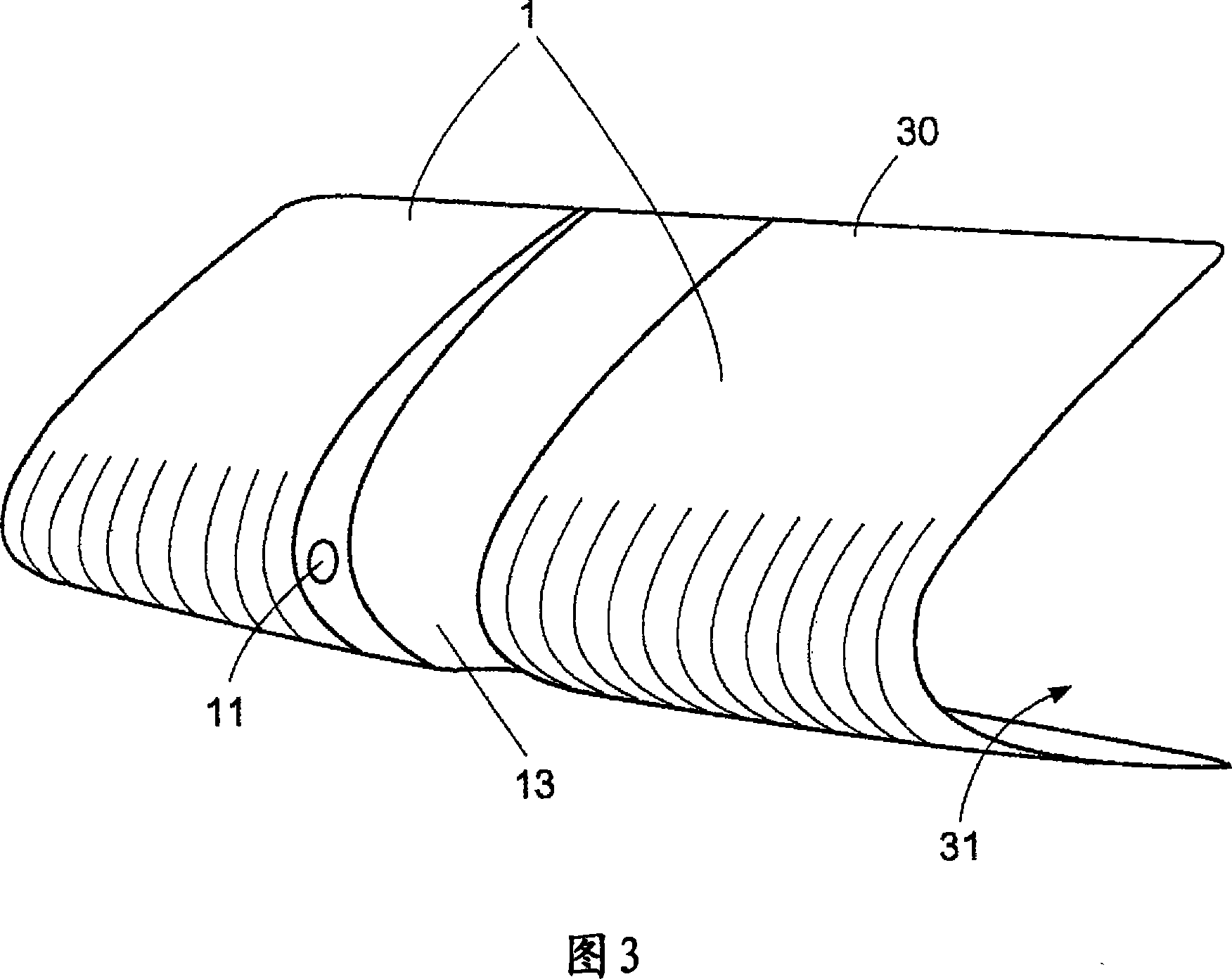
[0023] FIG. 2 shows a sectional view of a section of a rotor blade 30 of the wind power plant of FIG. 1 . Here, in particular, a section of the rotor blade in the region of the deposit sensor 1 is shown. The deposit sensor is installed in the region of the rotor blade nose 31 of the rotor blade 30 . The deposit sensor 1 basically consists of an optical transmitter 11 and an optical receiver 12 . The optical transmitter 11 is provided with a coupling-out lens 11a and the optical receiver 12 is provided with a coupling-in lens 12a. The optical transmitter 11 and the optica...


PUM


Abstract

Rotor blade (30) has rotor blade nose (31), deposition sensor device (1) arranged in the area of a rotor blade nose with a transmitter for wireless transmission of signals via a transmission link and receiver for receiving signals that are transmitted in a wireless manner via transmission link. Surface depositions can be detected in area of transmission link based on signals transmitted via transmission link. An independent claim is also included for the wind power station.

Description

technical field [0001] The invention relates to a rotor blade for a wind power plant and to a wind power plant with a corresponding rotor blade. Background technique [0002] In wind power plants, especially during the cold season, it is desirable to detect ice accretion on rotor blades in order to take suitable measures for deicing. Ice accumulation on rotor blades is undesirable because ice accumulation adds weight to the rotor blades. Furthermore, broken ice detached from the rotor blades during operation of the wind power plant can lead to dangerous bruises and damage to persons or property. In addition, broken ice breaking off from the rotor blades can lead to imbalances in the rotor blades, which ultimately necessitates the shutdown of the power station. However, it is not desirable to close the power station for economical reasons. [0003] In order to prevent this, many wind power plants have heating devices for the rotor blades in order to prevent ice accumulatio...

Claims


Application Information

Patent Timeline
Patent Type & Authority Applications(China)
IPC IPC(8): F03D11/00G01W1/00B64D15/20
CPCF05B2270/804Y02E10/722Y02E10/72F03D11/0091F01D25/02F05D2270/804Y02E10/721F03D11/0025F03D17/00F03D80/40
Inventor 艾劳埃斯·乌本
Owner 阿洛伊斯沃本
Learn More