
A power supply method and system for mobile phone

A technology of a power supply system and a power supply method, which is applied to electrical components, current supply devices, wireless communications, etc., and can solve problems such as complex circuits, low safety performance, and high manufacturing costs

Active Publication Date: 2011-02-02
SICHUAN JIUZHOU ELECTRIC GROUP +1
View PDF1 Cites 0 Cited by
  • Summary
  • Abstract
  • Description
  • Claims
  • Application Information

AI Technical Summary

Problems solved by technology

[0004] The present invention provides a mobile phone power supply method and system, which overcomes the shortcomings of high manufacturing cost, complex circuit and low safety performance in the background technology

Method used


Image

  • A power supply method and system for mobile phone
  • A power supply method and system for mobile phone
  • A power supply method and system for mobile phone

Examples


Embodiment 1

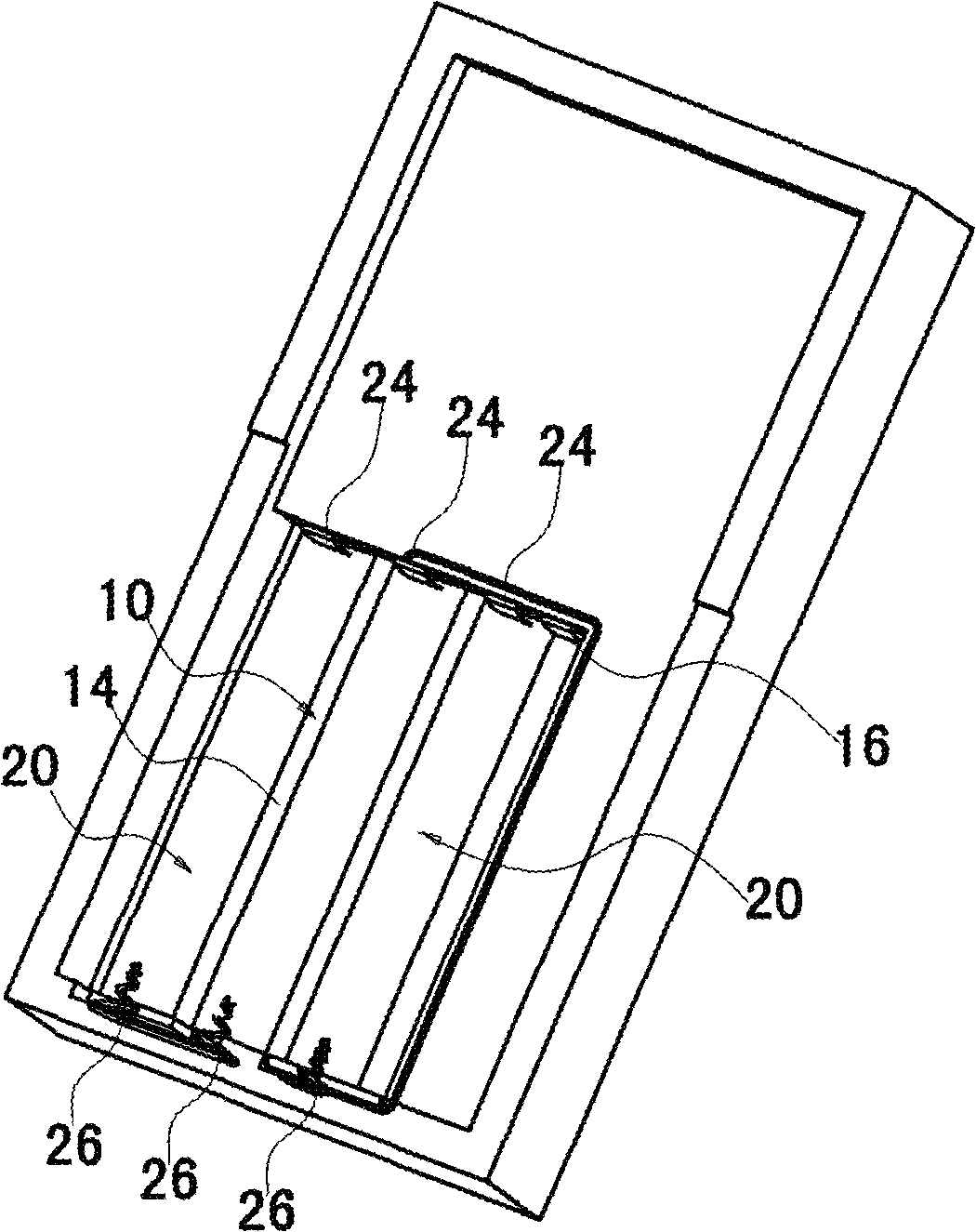
[0043] A mobile phone power supply system, which has a battery holder and a judgment module. Please check figure 1 as well as Figure 4 The battery holder includes an open cavity formed on the back of the mobile phone and a back cover 30 detachably connected to the open cavity. The open cavity and the back cover 30 cooperate to form a closed cavity. The closed cavity includes a cubic-shaped accommodating cavity 10, the bottom of the accommodating cavity 10 is concavely formed to form three longitudinally arranged arcuate cylindrical accommodating grooves 20, and the back cover 30 is concavely arranged on the inner side to form three longitudinally arranged The arc-shaped cylindrical accommodating groove 20 is arranged symmetrically with the three accommodating grooves 20 on the bottom surface of the accommodating cavity 10 and the inner surface of the back cover. Please check figure 2 as well as Figure 4 , After installing the back cover 30, the cube described the space of t...

Embodiment 2

[0087] A mobile phone power supply system, which has a battery holder and a judgment module. Please check Picture 9 The battery holder includes an open cavity formed on the back of the mobile phone and a back cover 30 detachably connected to the open cavity. The open cavity and the back cover 30 cooperate to form a closed cavity. The closed cavity includes a cubic arranging cavity 10, the bottom of the accommodating cavity 10 is recessed downward to form three horizontally arranged arcuate cylindrical accommodating grooves 20, and the back cover 30 is recessed on the inner surface to form three laterally arranged The arc-shaped cylindrical accommodating groove 20 is arranged symmetrically with the three accommodating grooves 20 on the bottom surface of the accommodating cavity 10 and the inner surface of the back cover. Please check Picture 9 as well as Picture 10 , After installing the back cover 30, the cube described the space of the cavity 10 and the structure of the lit...


PUM


Abstract

The invention discloses a handset power supply method and system. The method can realize a function that a handset is compatible with a disposable battery and a lithium battery. The method comprises following steps: a battery mounting step in which the lithium battery or the disposable battery is mounted in a handset battery seat; a judging step in which a handset CPU judges that the mounted battery is the disposable battery or the lithium battery, if the mounted battery is the lithium battery, a lithium battery power supply step is executed, and if the mounted battery is the disposable battery, a disposable battery power supply step is executed; the lithium battery power supply step in which the lithium battery supplies power to the handset, and the handset is set in a rechargeable mode;the disposable battery power supply step in which the disposable battery supplies power to the handset, and the handset is set in a non-rechargeable mode. The technique scheme of the invention firstly judges the mounted battery is the disposable battery or the lithium battery, then determines whether providing the chargeable mode, in this way, not only the lithium battery and the disposable battery power can be used as the power supply of the handset, but also battery explosion accidents induced by miss-charging can be avoided.

Description

Technical field [0001] The invention relates to a mobile phone power supply method and system. Background technique [0002] With the development of technology, the existing mobile phones not only have communication functions, but also have more and more auxiliary functions that consume a lot of power, such as MP3, MP4, camera and game functions, etc. The use of auxiliary functions will make the mobile phone battery The standby time and use time of the mobile phone are getting shorter and shorter, so there will often be such embarrassing or depressing experiences. The mobile phone cannot be used because the battery of the mobile phone is exhausted and cannot be charged in time. Please check Figure 14 , The circuit diagram of the existing ordinary mobile phone battery. The battery cell is generally a liquid lithium ion or polymer lithium ion cell. The positive and negative electrodes of the battery are connected to the positive and negative electrodes of the battery connector on t...

Claims


Application Information

Patent Timeline
Patent Type & Authority Patents(China)
IPC IPC(8): H04W88/02H04M1/73
Inventor 毛维铦林喆李晓峰
Owner SICHUAN JIUZHOU ELECTRIC GROUP
Learn More