Flow diverter and exhaust blower for vibrating screen separator assembly

Inactive Publication Date: 2005-01-04
MI +1
View PDF14 Cites 33 Cited by
  • Summary
  • Abstract
  • Description
  • Claims
  • Application Information

AI Technical Summary

Benefits of technology

The present embodiments of the invention provide a number of advantages. For example, the flow diverter assembly decelerates the flow of the materials thereby placing the materials onto the front most portion of the screen thereby enhancing the operational effectiveness of the screen during the separation of liquids and solid particles. Furthermore, the exhaust blower removes vapors from the materials that may be volatile and / or toxic thereby preventing explosions and / or harm to the human operators.

Problems solved by technology

Furthermore, the exhaust blower removes vapors from the materials that may be volatile and / or toxic thereby preventing explosions and / or harm to the human operators.

Method used


Image

  • Flow diverter and exhaust blower for vibrating screen separator assembly
  • Flow diverter and exhaust blower for vibrating screen separator assembly
  • Flow diverter and exhaust blower for vibrating screen separator assembly

Examples


Embodiment Construction

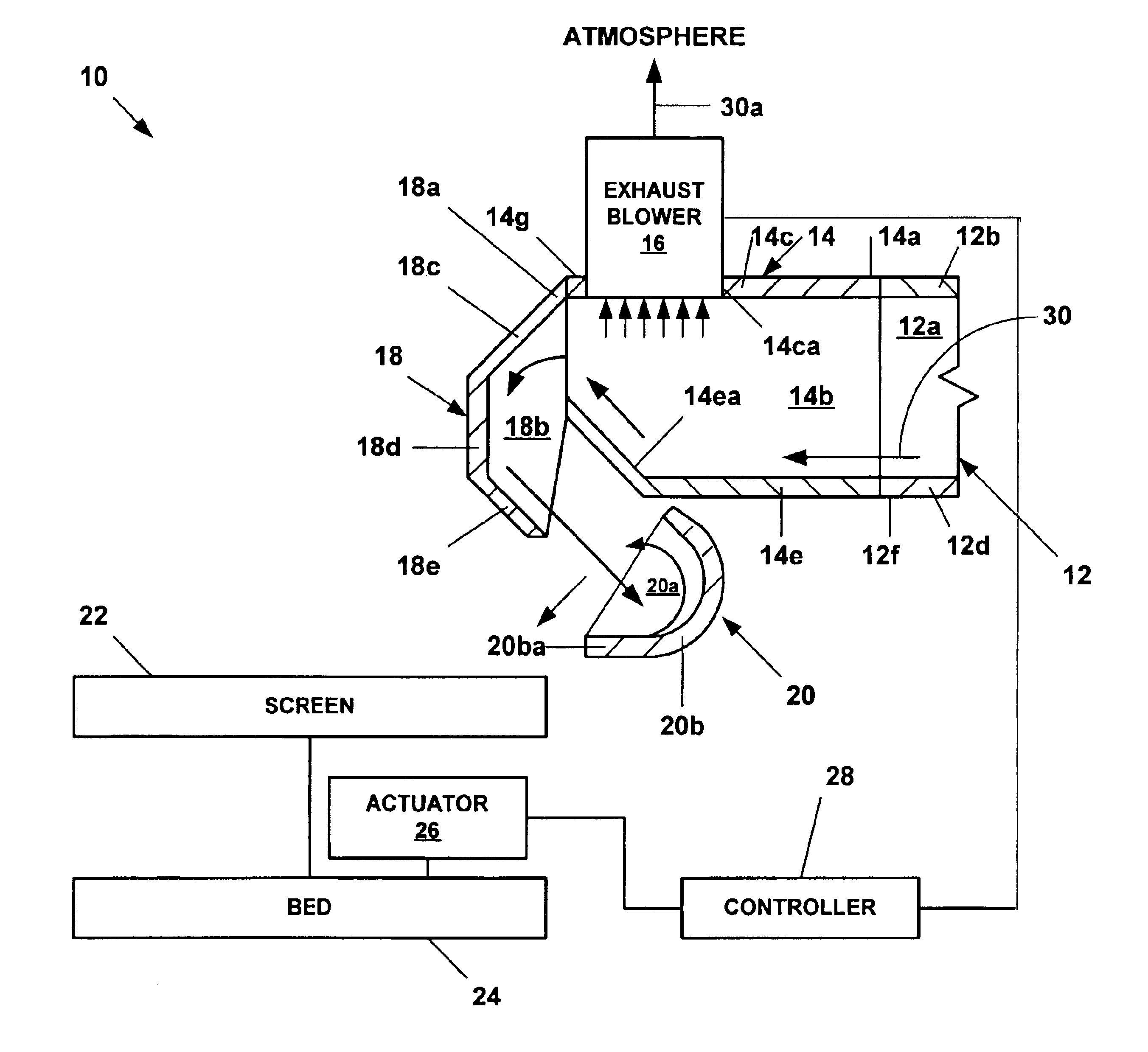
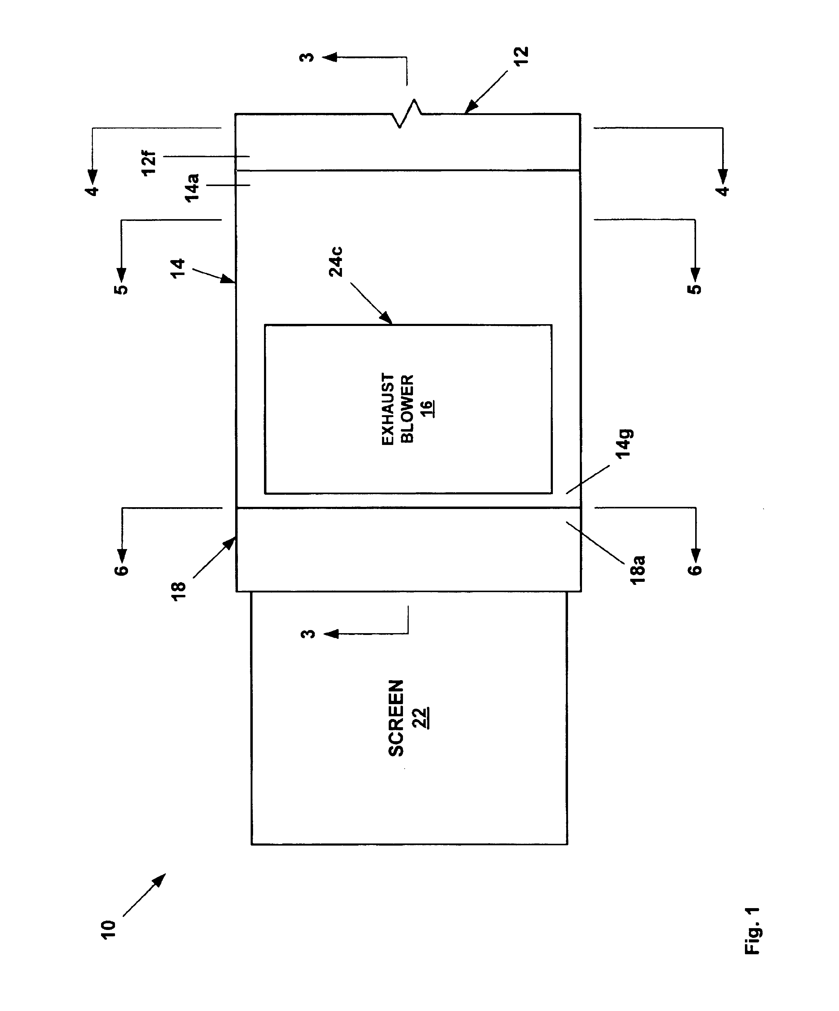
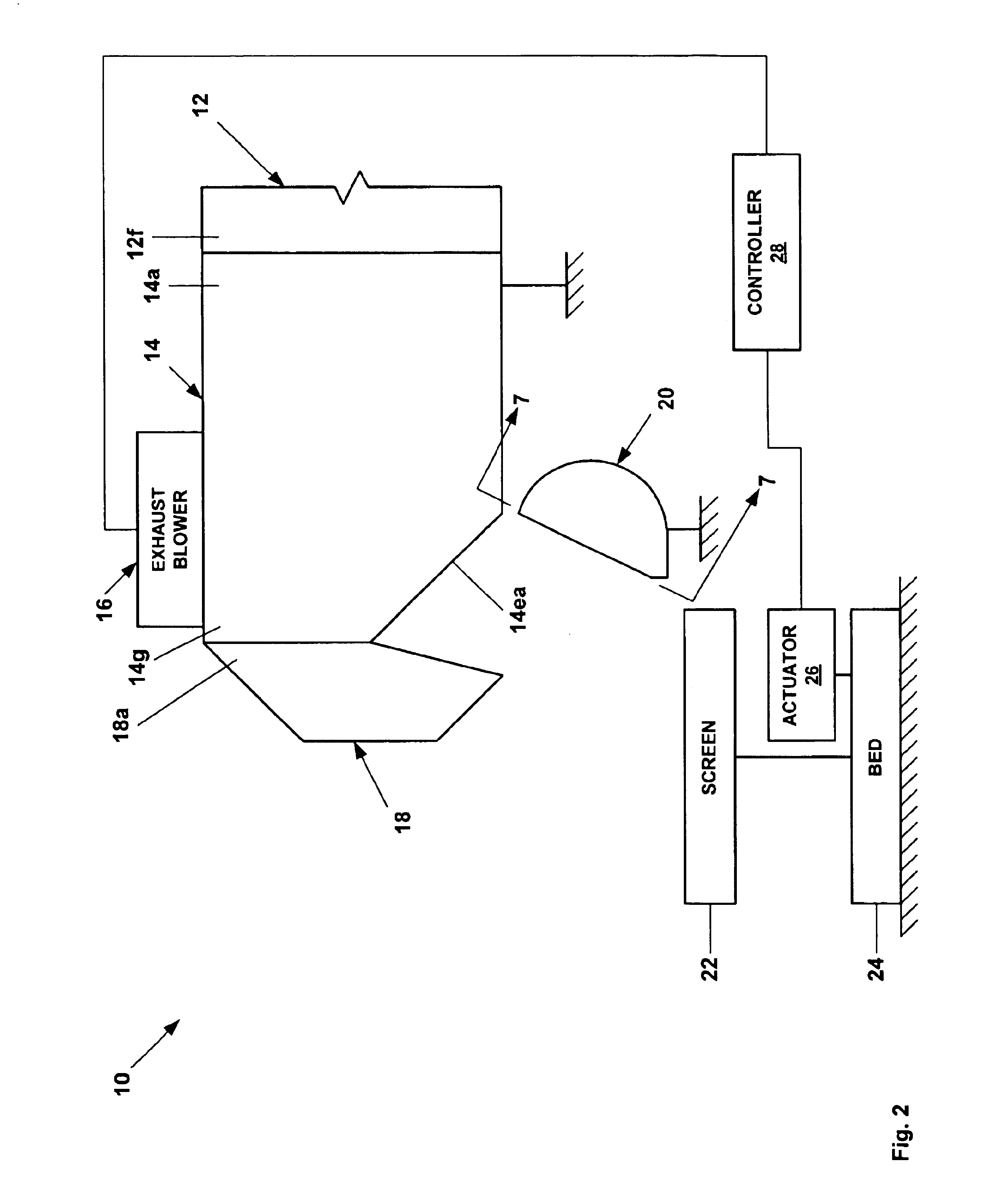
Referring to FIGS. 1-7, the reference numeral 10 refers, in general, to a vibrating screen separator assembly that includes a flow line 12 defining a passage 12a that includes side walls 12b, 12c, 12d, and 12e. An end 12f of the flow line 12 is coupled to an end 14a of a conduit 14 defining a passage 14b that includes side walls 14c, 14d, 14e, and 14f. The side wall 14c of the conduit 14 includes an opening 14ca for receiving the inlet of an exhaust blower 16 and the side wall 14e of the conduit includes a ramp 14ea that extends upwardly from the side wall toward the side wall 14c in the direction of another end 14g of the conduit. In an exemplary embodiment, the ramp 14ea is positioned approximately beneath the opening 14ca in the side wall 14c, and the angle of attack of the ramp ranges from about 35 to 55 degrees for reasons to be described.

An end 18a of an end wall 18 defining a passage 18b is coupled to the end 14g of the conduit that includes an upper inclined wall 18c, a vert...


PUM

PropertyMeasurementUnit
Surface areaaaaaaaaaaa

Abstract

A flow diverter and a vacuum blower for vibrating screen separator assembly. The flow diverter decelerates and increases the exposed surface of materials. The exhaust blower removes vapors from the materials.

Description

BACKGROUNDThis invention relates generally to screen separators, and in particular to flow diverters and exhaust blowers for screen separators.A typical screen separator consists of an elongated, box-like, rigid bed, and a screen attached to, and extending across, the bed. The bed is vibrated as the material to be separated is introduced onto the screen which moves the relatively large size material down the screen and passes the liquid and / or relatively small sized material into a pan. The bed can be vibrated by pneumatic, hydraulic, or rotary vibrators, in a conventional manner.Typically the material to be separated is conveyed onto the screen by directing the material from a flow line into the bottom of an open tank, commonly called a possum belly. The material fills the possum belly until it flows over a weir onto the screen. The weir is typically positioned such that the material falls on the beginning section of the screen. The possum belly acts as a fluid trap in which solids...

Claims


Application Information

Patent Timeline
IPC IPC(8): B07B13/00B07B13/16B07B1/46
CPCB07B13/16B07B1/46
Inventor FOUT, GARYSUTER, ROGER
Owner MI
Why Eureka
Try Eureka