Container in automobile

A technology for containers and vehicles, applied to pressure vessels, buses, outer walls of container structures, etc., can solve the problems of negative effects on dimensional stability, increased risk of warping, and cost

Active Publication Date: 2007-11-07
MAN NUTZFAHRZEUGE AG
View PDF1 Cites 6 Cited by
  • Summary
  • Abstract
  • Description
  • Claims
  • Application Information

AI Technical Summary

Problems solved by technology

However, the manufacture of the hem requires a certain amount of expense
Furthermore, in this case there is an increased risk of warping which can have a negative effect on dimensional stability

Method used


Image

  • Container in automobile
  • Container in automobile

Examples


Embodiment Construction

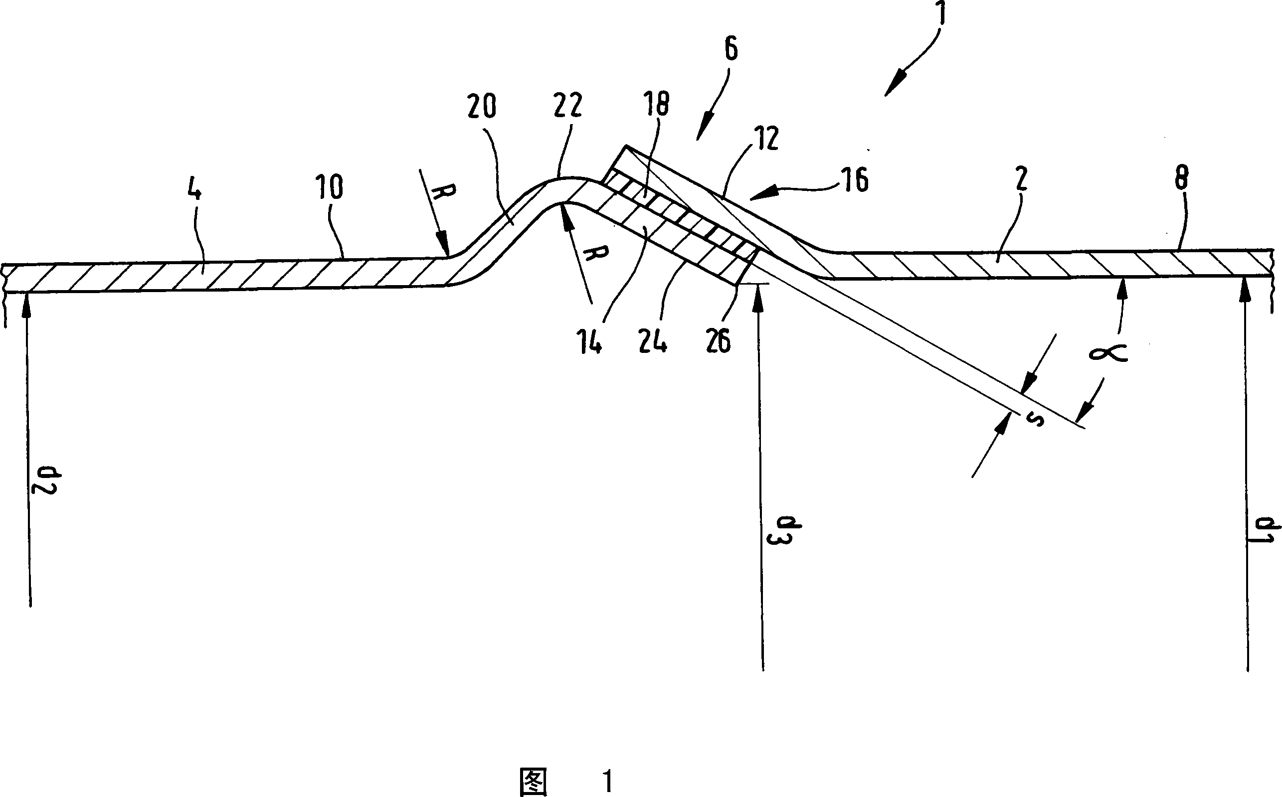
[0019] The container shown only in section in FIG. 1 and marked as a whole with 1 is preferably used as a compressed air container for storing compressed air for a compressed air brake system of a truck. Alternatively, the container can be used to store compressed air for any compressed air user in the vehicle, for example for pneumatic door operators, for compressed air springs or for other pneumatic vehicle devices or vehicle mechanisms.

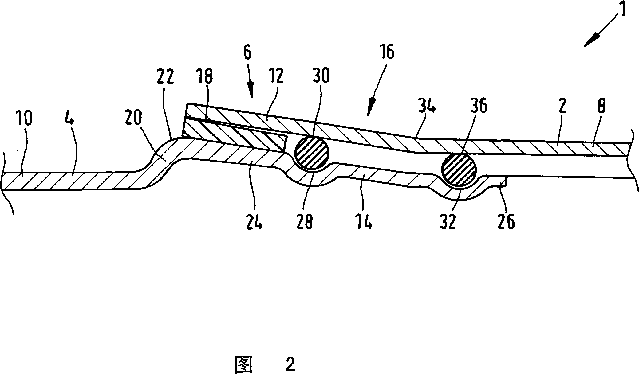
[0020] As shown in FIG. 1 , a compressed air container 1 is assembled, for example, from two container halves 2 , 4 of equal size, preferably with a circular cross section, which are joined to each other by their common connecting region 6 . Tightly connected. The container halves 2, 4 are preferably produced from a steel sheet provided with an anti-corrosion coating on the inner surface, which is formed into a cup-like shape by deformation, for example by deep drawing. This means that each of the container halves 2 , 4 consists of a bott...


PUM


Abstract

The container e.g. compressed air reservoir (1) has two cup-shaped container halves produced by recasting steel plates (2, 4), where edges (12, 14) of the halves overlap in an overlapping region. The edges are curved in a pointed angle opposite to cladding walls (8, 10) adjacent to the edges in such a manner that the edges run parallel to each other in the overlapping region. An adhesive- or butt joint (18) is arranged between the edges. The edge (12) of the container halves is curved outwards in the overlapping region, and the other edge (14) runs like a gable in a cross section.

Description

technical field [0001] The invention relates to a container for motor vehicles, in particular a compressed air container for trucks, according to the preamble of claim 1, the container comprising two cup-shaped container halves produced by deformation of steel plates, the The overlapping edges of the container halves in the overlapping region are connected to one another by gluing. Background technique [0002] Compressed air containers in trucks are used to store compressed air that is used as an operating medium for compressed air brakes and other devices in trucks, e.g. as compressed air springs, door operators or as crane or hoist operating medium. Furthermore, additional containers are used in the truck, for example fuel containers or urea containers. [0003] A compressed air container of this type is known from DE 199 57 855 A1. In this case, the edges of the container halves are not joined thermally, for example by gluing, so that damage to the anti-corrosion coat...

Claims


Application Information

Patent Timeline
IPC IPC(8): F17C1/00
CPCF17C1/00F17C2201/0104F17C2201/035F17C2201/056F17C2203/0636F17C2203/0658F17C2209/221F17C2209/227F17C2221/031F17C2223/0123F17C2223/035F17C2223/036F17C2260/011F17C2260/013F17C2260/053F17C2270/0171F17C2270/0176
Inventor M·蒂特尔N·伯格A·尤贝莱克T·莫桑迪尔
Owner MAN NUTZFAHRZEUGE AG
Why Eureka
Try Eureka