Variable compression ratio internal combustion engine

一种压缩比、内燃机的技术,应用在内燃活塞发动机、燃烧发动机、机械设备等方向,能够解决难以获得满意加速性能、时间延迟变长、增压器响应延迟大等问题

Inactive Publication Date: 2007-10-24
TOYOTA JIDOSHA KK
View PDF8 Cites 6 Cited by
  • Summary
  • Abstract
  • Description
  • Claims
  • Application Information

AI Technical Summary

Problems solved by technology

[0005] In the internal combustion engine using the above technology in combination, if the response delay of the supercharger is large, when an acceleration request is made to the internal combustion engine, for example, by depressing the accelerator pedal, the time delay between the accelerator pedal depression and the boost pressure increase becomes long , which sometimes makes it difficult to obtain satisfactory acceleration performance

Method used


Image

  • Variable compression ratio internal combustion engine
  • Variable compression ratio internal combustion engine
  • Variable compression ratio internal combustion engine

Examples


no. 1 approach

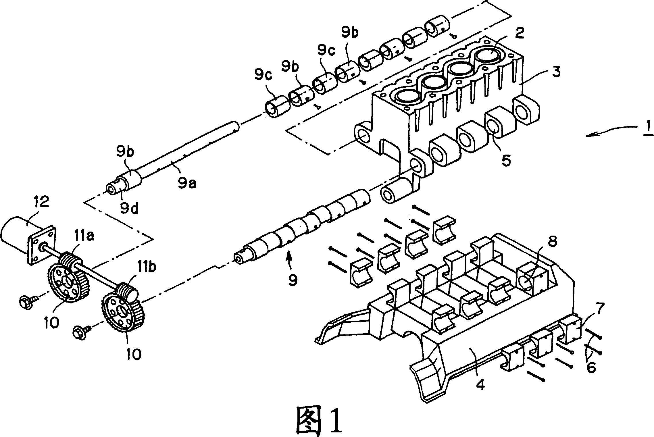
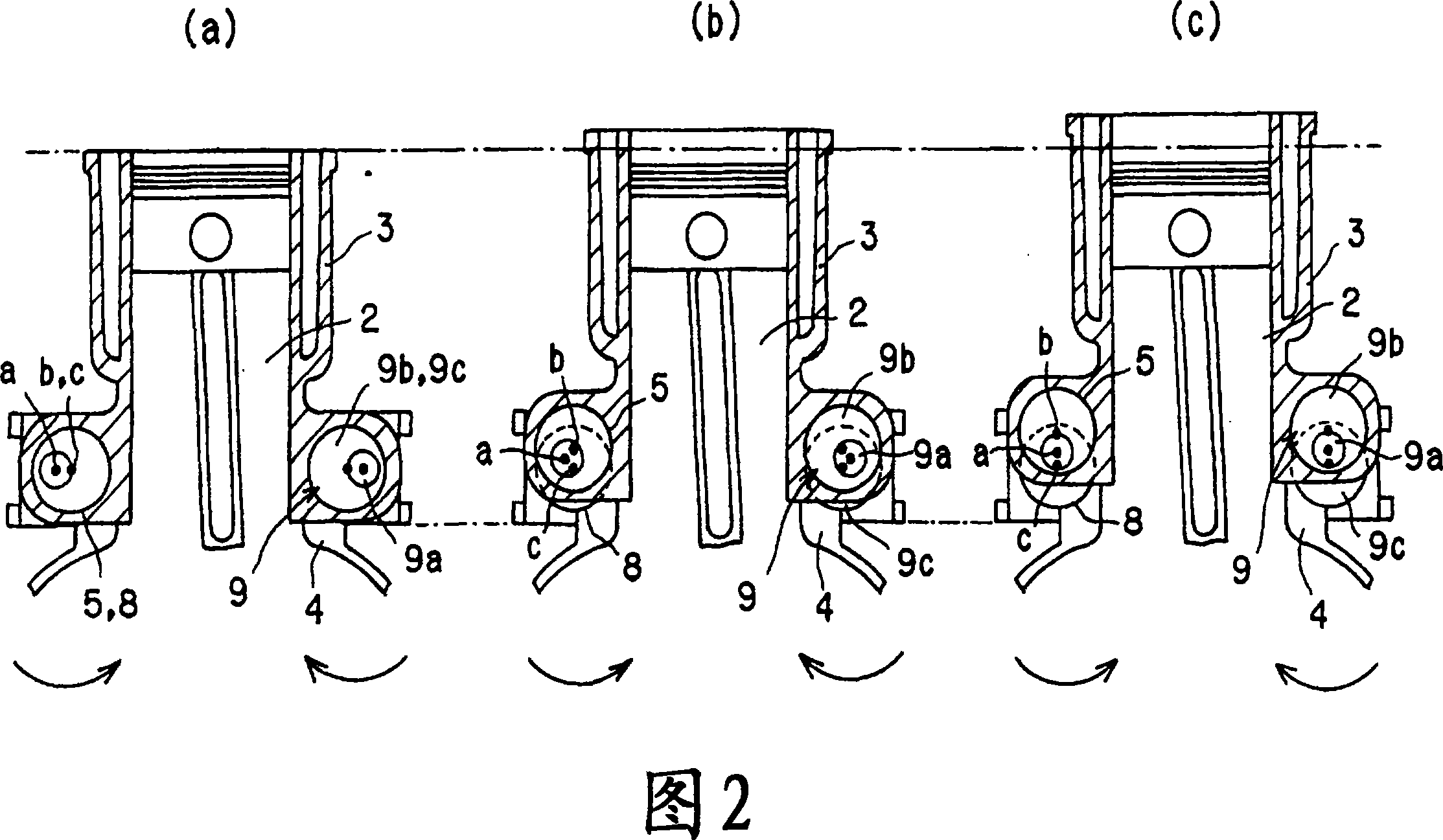
[0043] An internal combustion engine 1 to be described below is a variable compression ratio internal combustion engine in which the compression ratio is changed by moving a cylinder block 3 having cylinders 2 relative to a crankcase 4 to which pistons are coupled in the direction of the central axis of the cylinders 2 .

[0044] First, the structure of a variable compression ratio internal combustion engine according to this embodiment will be described with reference to FIG. 1 . As shown in FIG. 1, the cylinder block 3 has a plurality of protrusions formed on both sides of its lower portion. Each protrusion has a bearing receiving hole 5 formed therein. The bearing receiving hole 5 is cylindrical and extends perpendicular to the axial direction of the cylinder 2 and parallel to the arrangement direction of the plurality of cylinders 2 . The bearing accommodation holes 5 on one side are coaxially arranged, and a pair of axes of the bearing accommodation holes 5 on both sides...

no. 2 approach

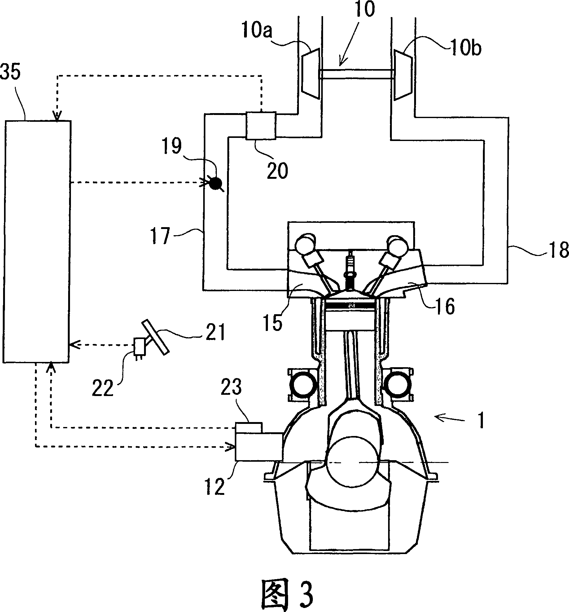
[0073] Next, a second embodiment will be described. In the second embodiment, when an acceleration request is made to the internal combustion engine, an optimum compression ratio at which engine torque becomes maximum is estimated, and the compression ratio is changed to the optimum compression ratio when an accelerator pedal is depressed.

[0074] Fig. 7 is a flowchart of the compression ratio changing routine at the time of acceleration in this embodiment. This program is a program stored in the ROM of the ECU 35, and is executed at predetermined time intervals after the internal combustion engine 1 is started.

[0075] In executing this process, it is first determined in step S101 whether or not an acceleration request has been made to the internal combustion engine 1 . Specifically, the depression stroke of the accelerator pedal 21 is detected by the accelerator position sensor 22, and it is determined whether the detection value is greater than or equal to a certain depr...


PUM


Abstract

The invention provides a technology that enables to control response delay of the supercharger in a variable compression ratio internal combustion engine under acceleration. When the variable compression ratio internal combustion engine is under acceleration, the compression ratio of the internal combustion engine is set to a compression ratio lower than a basic compression ratio that is so determined in accordance with the running condition of the internal combustion engine to realize a predetermined heat efficiency while suppressing knocking, thereby raising the exhaust gas pressure and shortening the response time of the supercharger.

Description

technical field [0001] The present invention relates to a variable compression ratio internal combustion engine in which the compression ratio can be changed. Background technique [0002] In recent years, techniques for making it possible to change the compression ratio of an internal combustion engine to improve the performance of the internal combustion engine in terms of mileage and power have been proposed. In the technology that has been proposed, as disclosed in Japanese Patent Application Publication Nos. 7-26981 and 2003-206771, the cylinder block and the crankcase are coupled in a manner that allows them to move relative to each other, and the camshaft is provided at their coupling portion The cylinder block and crankcase are moved toward and away from each other by turning the camshaft. [0003] In the aforementioned variable compression ratio internal combustion engine, the compression ratio of the internal combustion engine is changed according to its operating...

Claims


Application Information

Patent Timeline
Patent Type & Authority Applications(China)
IPC IPC(8): F02D41/10F02B75/04F02D41/00F02D15/04F02D23/00
CPCF02D41/10F02D41/0007F02B75/041Y02T10/144F02D35/02F02B37/00F02D15/04Y02T10/12
Inventor 秋久大辅神山荣一
Owner TOYOTA JIDOSHA KK
Why Eureka
Try Eureka