High power oxidation, reduction liquid energy-storage pile modular structure and its group mode
A liquid flow energy storage, high-power technology, applied in the field of stack modular structure and its group mode, can solve the problems of not meeting the requirements of large-scale production, affecting the normal operation of the stack, and low energy efficiency of the stack. Ensure cycle stability, proper cross-sectional area and length, and stable cycle performance
- Summary
- Abstract
- Description
- Claims
- Application Information
AI Technical Summary
Problems solved by technology
Method used
Image
Examples
Embodiment 1
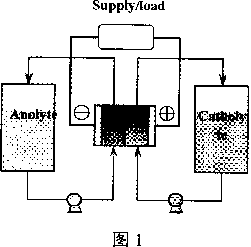
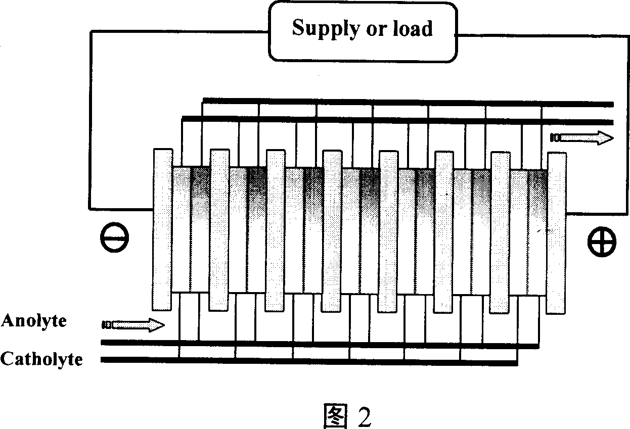
[0046] According to the proposed stack structure and group mode, this embodiment assembles a 10kW all-vanadium redox flow battery stack, including a set of electrolyte pumping device, 8 sub-stacks 5, and each sub-stack 5 contains a sub-unit 13. The sub-unit circuit is an external connection mode. Each sub-unit 13 contains 13 batteries. The liquid inlet mode is all parallel and equidistant in half. The common pipeline 3 for the electrolyte inlet of the stack is twice the cross-sectional area of the inlet and outlet shunts 41 and 42 for the electrolyte of the sub-stack, and the cross-sectional area of the common pipeline 3 for the electrolyte inlet of the sub-stack is the outlet of the electrolyte delivery pump 2 The cross-sectional area is 2 times, and the cross-sectional area of the sub-stack electrolyte inlet shunt 41 is three times the cross-sectional area of the common pipeline of the single battery; the electrode area of the single battery is 850cm 2 , the thickn...
Embodiment 2
[0049] The difference from Example 1 is that each sub-stack adopts two sets of sub-units with a back-to-back combination structure, the sub-unit circuits are built-in connection mode, the structure is more compact, the weight of the battery is reduced by 30%, and the thickness is reduced by 15%.
Embodiment 3
[0051] As shown in Table 1, it is a comparison table of stack current efficiencies of sodium polysulfide / bromine redox flow energy storage battery subunits with two parameter structures. This embodiment will use two different structural parameters of sodium polysulfide / bromine The subunits of the bromine redox flow energy storage battery are compared. The liquid enters and exits from the front of the liquid inlet end plate of a subunit. The cross-sectional area of the pipeline is 0.5cm 2 , the thickness of the single battery is 1.5cm, and the cross-sectional area of the common pipeline of the subunit I is 1.5cm 2 , the thickness of the single battery is 1.0cm, and the cross-sectional area of the liquid inlet shunt of the subunit II is 0.12cm 2 , the length is 15cm, and the cross-sectional area of the liquid inlet shunt of the subunit I is 0.24cm 2 , the length is 8cm; each resistance parameter is converted by the formula R=K×L / S, where L is the length of each liquid ...
PUM
 Abstract
Description
Claims
Application Information
 - R&D
- Intellectual Property
- Life Sciences
- Materials
- Tech Scout
- Unparalleled Data Quality
- Higher Quality Content
- 60% Fewer Hallucinations
Browse by: Latest US Patents, China's latest patents, Technical Efficacy Thesaurus, Application Domain, Technology Topic, Popular Technical Reports.
© 2025 PatSnap. All rights reserved.Legal|Privacy policy|Modern Slavery Act Transparency Statement|Sitemap|About US| Contact US: help@patsnap.com


