
Battery voltage measurement circuit, battery voltage measurement method, and battery electric control unit

A battery voltage and circuit technology, applied in the direction of measuring devices, measuring current/voltage, circuits, etc., can solve the problems of inability to obtain accuracy, deterioration of detection voltage accuracy, and inability to obtain gain, and achieve the effect of low price

Inactive Publication Date: 2007-09-26
KEIHIN CORP
View PDF4 Cites 29 Cited by
  • Summary
  • Abstract
  • Description
  • Claims
  • Application Information

AI Technical Summary

Problems solved by technology

[0010] However, in the aforementioned conventional methods, like the methods shown in Patent Document 1 and Patent Document 2, the reference voltage of the first-stage amplifier or converter that detects the input cell voltage is set to be in the middle of the lowest terminal or the battery pack. When the virtual ground terminal of the same potential is touched, the input voltage to the primary amplifier or converter increases, a large gain cannot be obtained, and there is a problem that the detection voltage accuracy deteriorates.
In addition, there are also problems such as an increase in dark current, and from this point of view, there is a problem that sufficient accuracy cannot be obtained.
In addition, in the example of the flying capacitor type shown in Patent Document 3 and the like, the high-voltage part on the battery side is insulated from the low-voltage part at the ground potential of the vehicle body, so components are required to have a bidirectional withstand voltage. Large components, so there is a cost problem
In addition, there is a problem that, in the structure where switching is performed by a switch in order to input to a common microcomputer and A / D converter as in Patent Document 3 and Patent Document 4, it is easily affected by noise due to parasitic capacitance and the like.
In addition, in the structure of measuring with the vehicle body ground as a reference as in Patent Document 4, the reference potential of the battery pack is insulated from the vehicle body potential, so noise that is difficult to determine the cause is likely to occur, and there is a possibility that it is easily affected by spurious noise. question

Method used


Image

  • Battery voltage measurement circuit, battery voltage measurement method, and battery electric control unit
  • Battery voltage measurement circuit, battery voltage measurement method, and battery electric control unit
  • Battery voltage measurement circuit, battery voltage measurement method, and battery electric control unit

Examples


Embodiment Construction

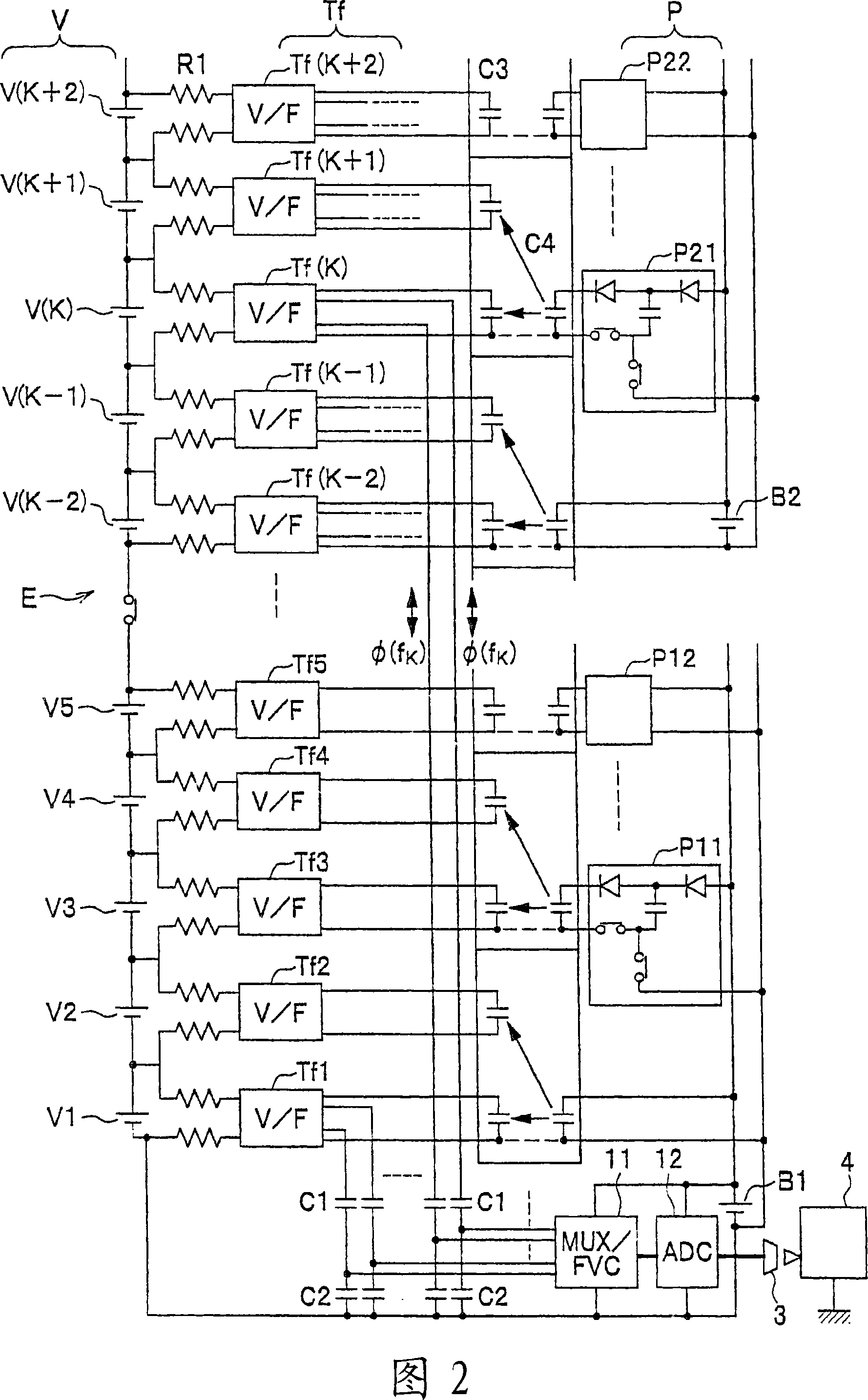
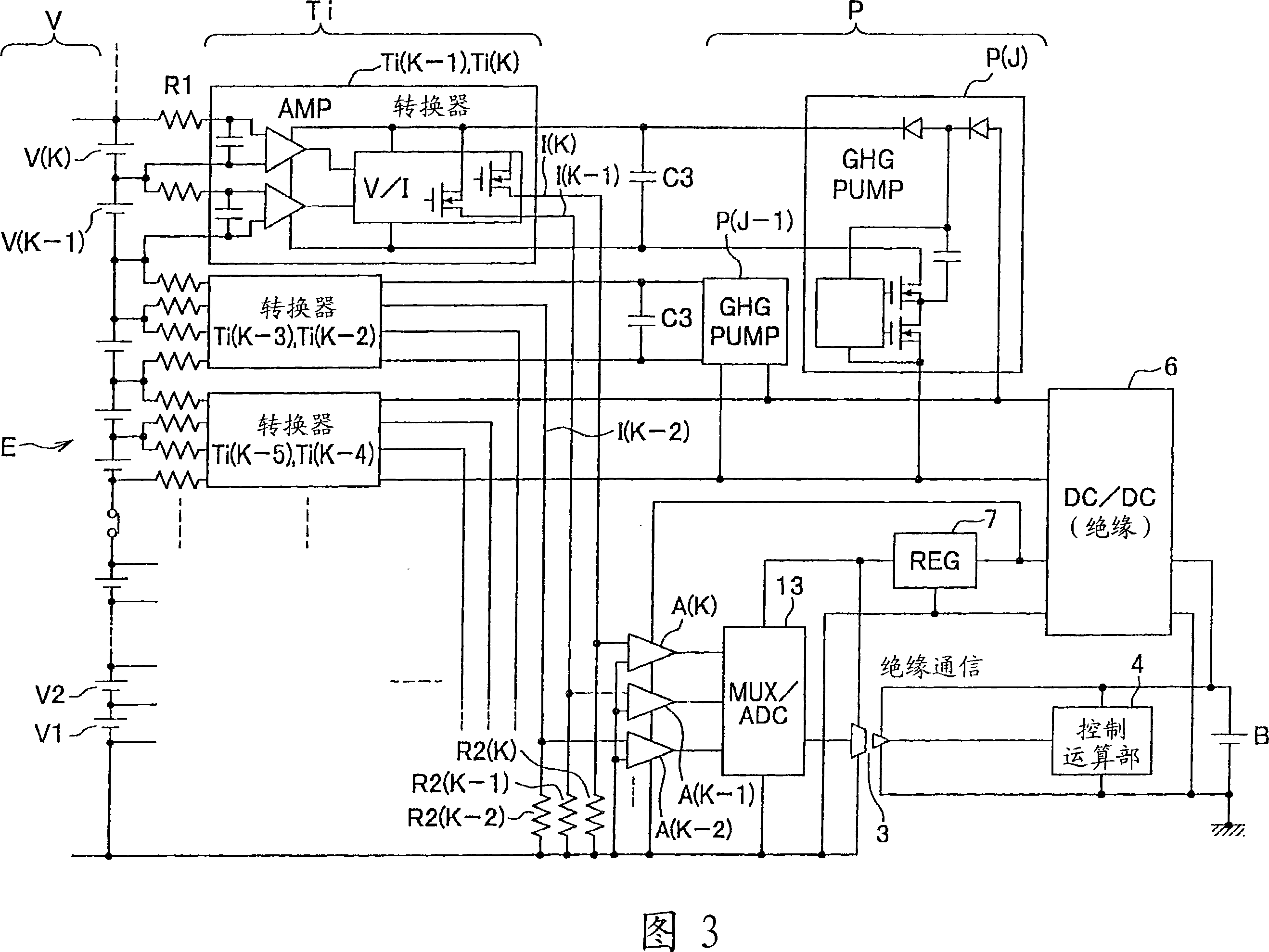
[0040] Hereinafter, the present invention will be specifically described with reference to the drawings.

[0041] In addition, when the same element is shown in a plurality of drawings, the same reference numeral is given.

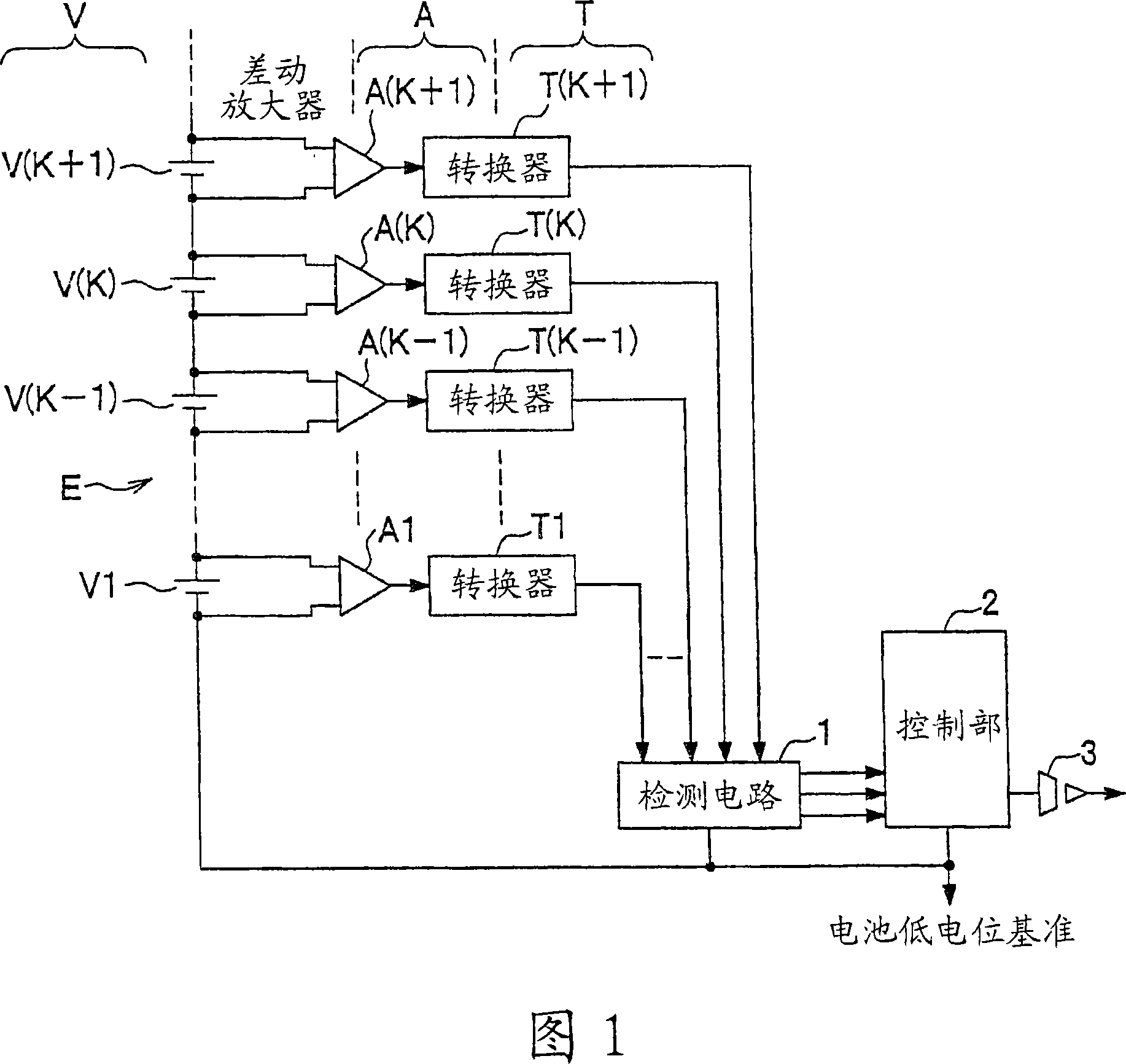
[0042] Fig. 1 is a schematic block diagram of a battery voltage measuring circuit of the present invention. In Figure 1, the numbers behind the labels V, A, and T are additional marks for identification. When using K (integer) and the number after adding and subtracting K as additional marks, add parentheses () after K. expression. Symbol E denotes a battery pack to be measured. Reference numerals V1, . . . , V(K), . Reference numerals A1, . . . , A(K), . Symbols T1, . . . , T(K), . Reference numeral 1 denotes a detection circuit, which reversely converts the physical quantities converted by the converters T1, ..., T(K), ... into electrical signals with the lowest potential of the battery pack E as a reference (for example, voltages corresponding to V...


PUM


Abstract

The invention provides a battery voltage measurement circuit, a battery voltage measurement method and a battery electronic control device. The object is to precisely measure a battery voltage by a simple and low-cost structure and via a common measurement circuit. As a solving means, voltages at two ends of each unit battery V are amplified by a differential amplifier A, and are converted to special physical quantities corresponding to the voltages at two ends of each unit battery V by a converter T, voltage levels are performed with shift by a detection circuit (1), and are inversely converted into voltages using a lowest level of the battery as a common reference level. In addition, the inversely converted voltages are orderly selected in a multi-path scanner by a control portion (2) to perform an A / D conversion, serial digital signals are transmitted to a control calculation portion (4) via an insulative buffer circuit (3).

Description

technical field [0001] The present invention relates to a technique for measuring the voltage of each unit cell constituting a battery pack in which a plurality of unit cells are connected in series. Background technique [0002] In hybrid vehicles, electric vehicles, fuel cell vehicles, etc., for the purpose of reducing wiring resistance loss and miniaturization of switching elements, etc., a high-voltage battery pack is generally composed of unit cells composed of multiple secondary batteries or fuel cells connected in series. . For example, when using a fuel cell, the voltage of a single cell of a unit cell is about 1V, so generally hundreds of single cells are connected in series to obtain the required high voltage. In this case, if one of the unit cells is abnormal and operates at an extremely low or extremely high voltage, the unit cell that has such a defective unit cell may be corroded, resulting in poor withstand voltage, result in damage to the entire battery pac...

Claims


Application Information

Patent Timeline
Patent Type & Authority Applications(China)
IPC IPC(8): H01M10/48G01R31/36G01R19/00
CPCG01R31/3658G01R31/362G01R31/396G01R31/3835
Inventor 镰田诚二
Owner KEIHIN CORP
Learn More