Polarized light splitting device and method for manufacturing the same

A technology for separating components and polarizing light, which is applied in the direction of optical components, optics, instruments, etc., can solve problems such as deterioration of optical characteristics, and achieve the effect of preventing deterioration of optical characteristics

Inactive Publication Date: 2007-09-19
TOYO TSUSHINKI
View PDF3 Cites 13 Cited by
  • Summary
  • Abstract
  • Description
  • Claims
  • Application Information

AI Technical Summary

Problems solved by technology

[0012] However, in the above-mentioned polarized beam splitter 100 formed with the polarized light separation film 110, as shown in FIG. There is a problem of cracks and deterioration of optical characteristics

Method used


Image

  • Polarized light splitting device and method for manufacturing the same
  • Polarized light splitting device and method for manufacturing the same
  • Polarized light splitting device and method for manufacturing the same

Examples


Embodiment Construction

[0033] Hereinafter, embodiments of the present invention will be described.

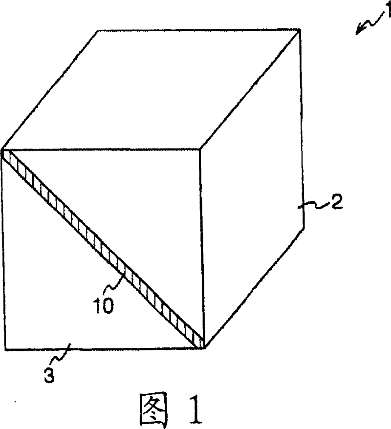
[0034]FIG. 1 is a diagram showing the structure of a polarization separation element according to an embodiment of the present invention.

[0035] The polarized beam splitter (polarized light splitting element) 1 of this embodiment shown in FIG. 1 is configured as a cube by joining two right-angled triangular prisms 2 and 3 through a polarized light splitting film 10, for example, it has a predetermined Polarized light components (P polarized light) are transmitted, and on the other hand, other polarized light components (S polarized light) are reflected.

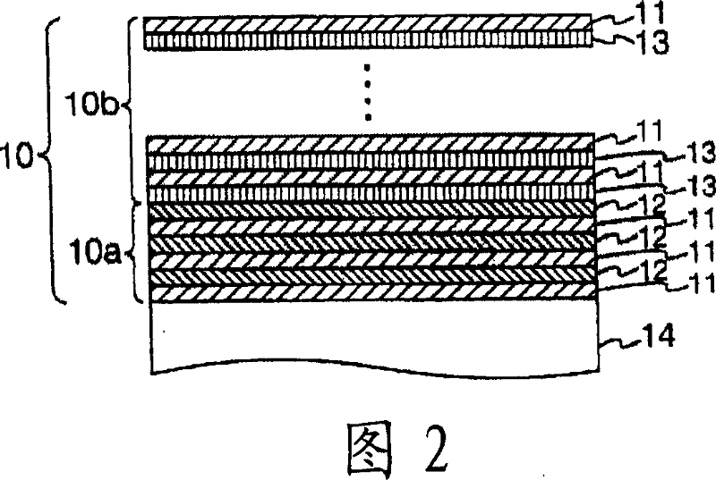
[0036] The polarized light separation film 10 is a film having a property of selectively transmitting either S-polarized light and P-polarized light, and selectively reflecting the other. In addition, the polarized light separation film 10 will be described later.

[0037] In addition, in the polarization beam splitter 1 of the present embodiment conf...


PUM


Abstract

To provide a polarized beam splitter free from peeling of a polarized light splitting film or cracks on an interface with a prism.The polarized light beam splitter 1 comprises two right triangular prisms bonded to each other at inclined surfaces thereof via a polarized light splitting film 10, wherein the polarized light splitting film 10 comprises a first polarized light splitting film layer 10a formed by alternately laminating SiO2coatings 12 having compressive stress and lanthanum titanate films 11, and a second polarized light splitting film layer 10b formed by alternately laminating MgF2films 13 having tensile stress and lanthanum titanate films 11.

Description

Technical field [0001] The present invention relates to a polarization separation element and a manufacturing method thereof, and is particularly suitable for an optical pickup of an optical disc recording and reproducing device. Background technique [0002] 7 is a diagram illustrating the structure and method of use of a conventional polarization beam splitter (polarized light splitting element) used in an optical pickup of an optical disc and a magneto-optical disk recording and reproducing device. [0003] The polarization beam splitter 100 shown in FIG. 7(a) is formed into a cube by joining two triangular prisms 101 and 102 via a polarization separation film 110, and has, for example, a predetermined polarized light component (P polarized light) transmitted therethrough. On the other hand, it has the function of reflecting other polarized light components (S polarized light). Therefore, when the polarized light separating element 100 constructed in this way is applied to an ...

Claims


Application Information

Patent Timeline
Patent Type & Authority Applications(China)
IPC IPC(8): G02B27/28
Inventor 古里大喜
Owner TOYO TSUSHINKI
Why Eureka
Try Eureka