
Multifunctional window

A multi-functional, window sash technology, applied in the direction of door/window accessories, wing leaf arrangement, wing leaf parts, etc., can solve the problems of easy failure, many processing parts, high cost, etc., to achieve less failure and overcome angle constraints , Good rigidity and strength

Inactive Publication Date: 2007-09-19
贺云强
View PDF1 Cites 5 Cited by
  • Summary
  • Abstract
  • Description
  • Claims
  • Application Information

AI Technical Summary

Problems solved by technology

[0003] 1. The multifunctional window with the patent application No. 0112849 has 3 rails and 3 wheels of the horizontal frame profile and 12 scattered points installed on the square tubes in the upper and lower horizontal frames, and the scatter point with 18 wheels installed on the slightly wider window sash is complicated. , It is difficult to debug. It is only the operation of the two large wheels in the lower frame and the 2-4 small wheels in the upper frame.
[0004] 2. The patent application No. 0239019.1 of the multi-functional window discloses the scheme. Their grooves are too deep. When the sash is closed, there is always a groove exposed. Once there is a sandstorm, the groove will be filled, and the sash will be difficult to open again. The dust that falls into it is also difficult to clean
[0006] 4. The two inventions require too many profiles to make windows, consume a lot, have many and complicated parts, have too many processing parts, and the cost is very high
[0007] 5. Since the window sashes of the two inventions have many parts and are easy to break down, they need to be replaced soon after use
[0008] Although the multifunctional window that the patent application number is 200420034529.7 improves and simplifies a lot for this reason, there are still many places that must make significant simplification and improvement, so that the window is more perfect

Method used


Image

  • Multifunctional window
  • Multifunctional window
  • Multifunctional window

Examples


Embodiment Construction

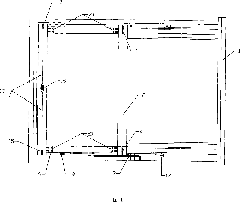
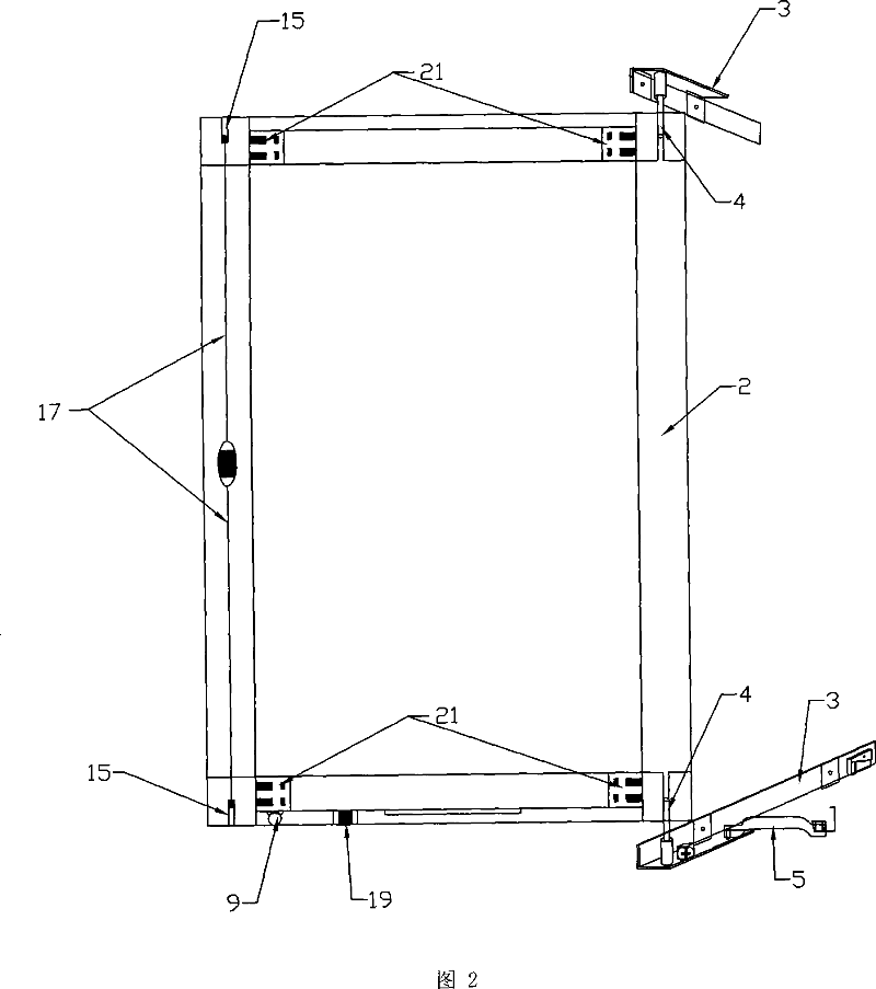
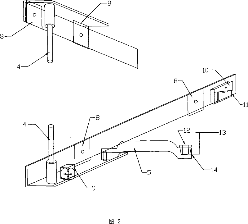
[0034] In the embodiment shown in Fig. 1, the track of the window frame 1 is a double-track parallel step slideway profile 22, wherein the structure of the single track includes a vertical side track and a horizontal side track, and a horizontal groove is provided on the vertical side track. As shown in Figure 5. The window frame 1 is fixed on the window opening, and each pair of monorails of the upper and lower window frames 1 is provided with a long sash support arm 3 opposite to each other. One side of the sash support arm 3 is a right angle formed by a vertical side and a horizontal side, and the sash support arm 3 The other side is composed of a vertical side alone, as shown in Figure 3; a window frame slider 8 is fitted in the track groove of the vertical side of the window frame 1, and the built-in screw on the window frame slider 8 is horizontal outside, and the sash support arm 3 is placed on the single rail of the window frame 1, the mounting holes opened on the vert...


PUM


Abstract

The invention discloses a multifunctional window for house building, characterized in that up-down window frames mounted in the window opening are relatively equipped with window leaf supporting arms moving on the window frame, side rabbet on the window leaf is movably fixed on stationary rotary shaft of the window leaf supporting arm, one end of the supporting rod is hinged on the window leaf supporting arm, the other end of the supporting rod is movably hinged on window leaf up-down horizontal bottom, and the window leaf can be opened in a range of 0 degree to 180 degrees. The window leaf supporting arms and the window leaf up-down horizontal bottom are equipped with rolling wheels, locking bolt sleeve-rack in another side rabbet of the window leaf is provided with a length-adjustable locking bolt; the window leaf supporting arm is also provided with window moving locking mechanism, the window leaf is automatically locked on the window frame by moving the locking mechanism when the window leaf is closed. The window leaf is also provided with a angle opening stopping device which can fix the window leaf in a certain opening position. The invention also discloses a fastening connection structure between the up-down horizontations of the window leaf and the left-right side rabbets.

Description

(1) Technical field: [0001] The invention relates to a multifunctional window for house construction. (two) background technology: [0002] In recent years, open casement, rotating, and sliding windows have their own characteristics. For example, the patent application No. 0112849 and the patent application No. 0239019.1 disclose two kinds of multifunctional windows. Although they integrate the function of pushing and pulling horizontally and externally rotating 180 degrees, they have great innovations, but their shortcomings are: [0003] 1. The multifunctional window with the patent application No. 0112849 has 3 rails and 3 wheels of the horizontal frame profile and 12 wheel scatter points installed on the square tubes in the upper and lower horizontal frames, and the scatter point with 18 wheels installed on the slightly wider window sash is complicated. , debugging difficulty, it is only the operation that two big wheels of lower frame and 2-4 small wheels center of gra...

Claims


Application Information

Patent Timeline
IPC IPC(8): E06B3/50E05C17/18E05C17/60
Inventor 贺华生贺云强
Owner 贺云强
Learn More