
Detecting method of rubber material and detecting device

A detection method and technology of adhesive material, which are applied to measurement devices, optical devices, semiconductor/solid-state device testing/measurement, etc., can solve the problems of low gray value of detection points, detection errors, and different gray values, etc. Achieve the effect of improving product quality, increasing accuracy, and increasing correctness

Inactive Publication Date: 2007-09-12
AU OPTRONICS CORP
View PDF0 Cites 6 Cited by
  • Summary
  • Abstract
  • Description
  • Claims
  • Application Information

AI Technical Summary

Problems solved by technology

[0005] However, due to process factors or material factors, the gray value of each conductive line is different. Therefore, when counting the gray value of this detection point, it will be affected by the different gray value of each conductive line.
When the color of the conductive line is too bright, it is easy to make the gray value of the detection point too high, and the printed circuit board with anisotropic conductive adhesive is misjudged as not attached with anisotropic conductive adhesive
When the color of the conductive line is too dark, it is easy to make the gray value of the detection point low, and the printed circuit board without anisotropic conductive adhesive is misjudged as an anisotropic conductive adhesive.
This will lead to detection errors and cannot effectively improve the quality of the product

Method used


Image

  • Detecting method of rubber material and detecting device
  • Detecting method of rubber material and detecting device
  • Detecting method of rubber material and detecting device

Examples


no. 1 example

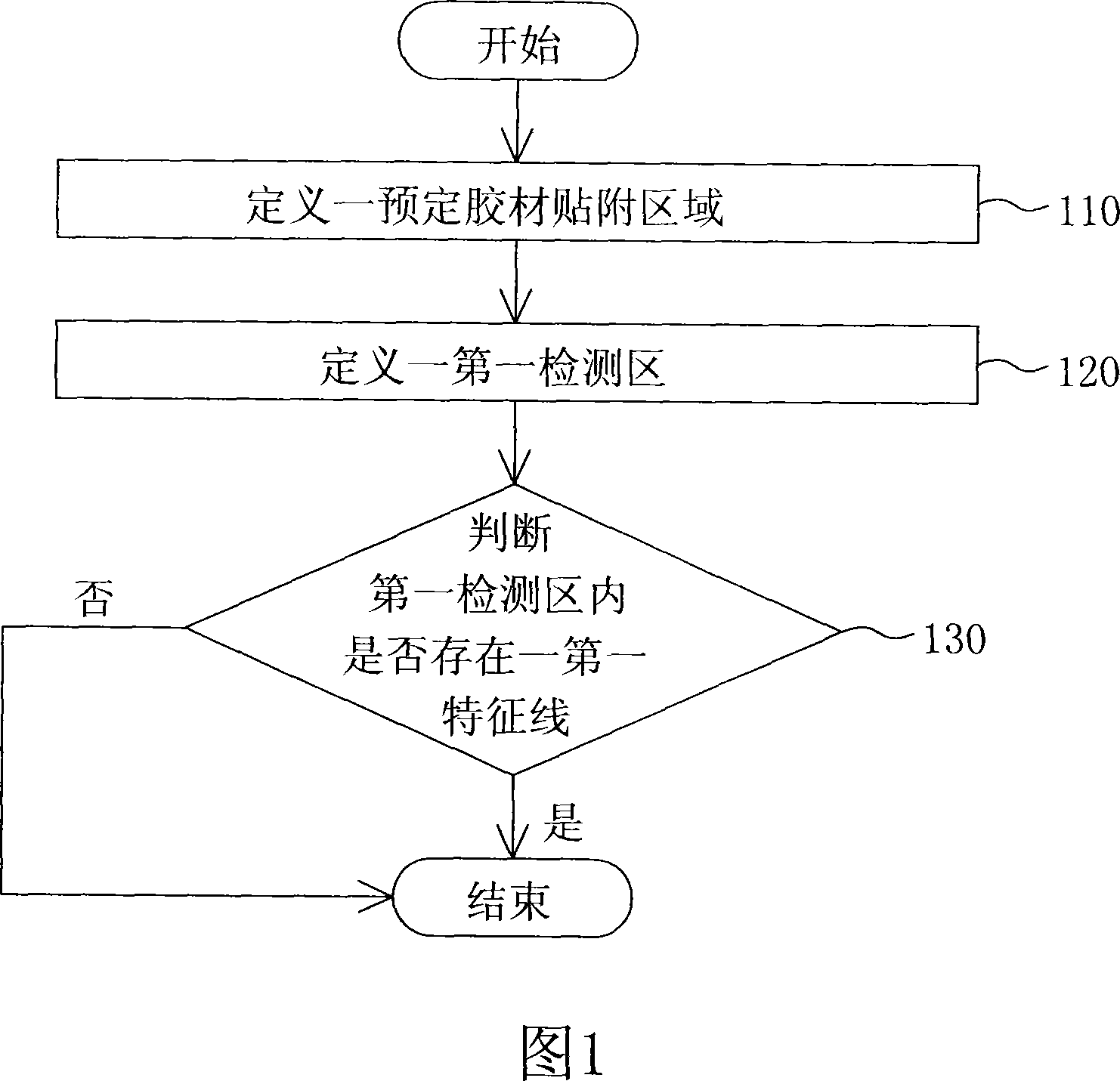
[0031] The adhesive detection method according to the first embodiment of the present invention is used to detect the adhesion status of an adhesive attached to a surface. Please refer to FIG. 1 , which is a flow chart of a detection method for adhesive materials according to a first embodiment of the present invention. A plurality of conductive circuits are arranged on the surface, where the conductive circuit is attached with glue corresponding to a first gray value, and where the conductive circuit is not attached with adhesive corresponds to a second gray value. This detection method includes the following steps.

[0032] Firstly, as shown in step 110 , a predetermined adhesive attachment area is defined on the surface, and the predetermined adhesive attachment area has a first edge.

[0033] Next, define a first detection area on the surface, as shown in step 120 . The first detection area covers a part of the first edge.

[0034] According to the detection method of t...

no. 2 example

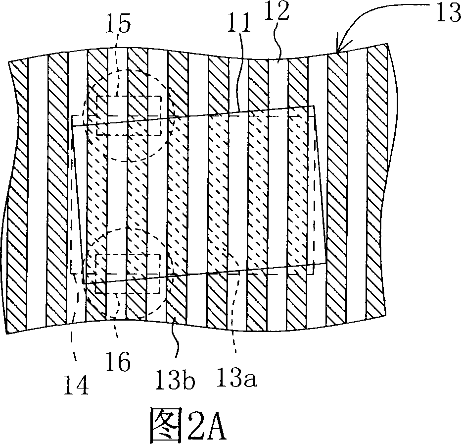
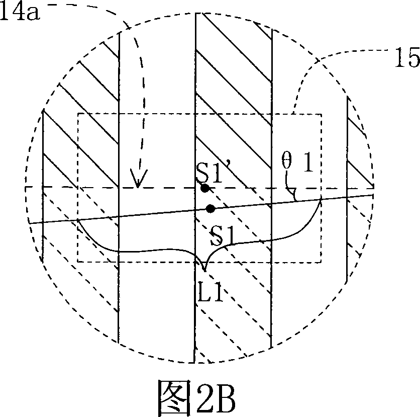
[0037] Please refer to Figures 2A to 5B at the same time. Figures 2A to 2C are schematic diagrams of adhesive materials to be detected attached to the surface in the detection method according to the second embodiment of the present invention; Schematic diagrams of the detection area, the predetermined adhesive attachment area, and the adhesive; FIG. 4 to FIG. 5B are flow charts of the adhesive detection method according to the second embodiment of the present invention. The adhesive material 11 is attached to the surface 12, and a plurality of conductive circuits 13 are disposed on the surface 12, as shown in FIGS. 2A-2C . The portion 13a of the conductive circuit 13 with the adhesive material 11 attached corresponds to a first grayscale value, and the portion 13b of the conductive circuit 13 without the adhesive material 11 corresponds to a second grayscale value. In this embodiment, the surface 12 is, for example, the surface of a printed circuit board (Printed Circuit Board,...


PUM


Abstract

This invention disclose a glue material test method and detection device, used for detecting sticking status of one glue material attaching on one surface; This surface set multiterm electric conduction line. On this electric conduction line, sticking glue material place correspond first grey scale value, whereas not sticking glue material place correspond second grey scale value. Test method includes following steps: first, prearrange a glue material sticking region on this surface, this region possess a fist verge; secondly, define a first detection area on this surface, which cover segmental first verge; then detect multi- first detection point's grey scale value within first detection area, and base on first and second grey scale value to judge whether within first detection area present first typical line that represent glue material has stocked. This invention can by midpoint of first typical line and midpoint of second typical line to judge glue material's sticking width whether abnormity, also can by first offset and second offset to judge glue material's sticking excursion status whether abnormity.

Description

technical field [0001] The invention relates to a detection method and a detection device for adhesive materials, in particular to a detection method and a detection device for the accuracy of adhesive material attachment. Background technique [0002] In recent years, planar display devices are becoming more and more popular among consumers due to their small size, light weight and low radiation. In addition, due to the advancement of technology, the display quality of the planar display device can be greatly improved, while the production cost can be continuously reduced, so that the price of the planar display device can tend to be popularized, further increasing the market share. Among various planar display devices sold in the market, liquid crystal display devices are the most popular and have become indispensable electronic products in modern homes or offices. [0003] In the manufacturing process of general thin-film transistor liquid crystal displays, a technology ...

Claims


Application Information

Patent Timeline
Patent Type & Authority Applications(China)
IPC IPC(8): G01N21/88G01B11/26H01L21/66
Inventor 王益
Owner AU OPTRONICS CORP
Learn More