Steam and vacuum cleaner

A technology of vacuum cleaning and steaming, which is applied in the direction of cleaning carpets, cleaning floors, cleaning machinery, etc. It can solve the problems of steam inhalation, unsightly, short-circuit accidents, etc., and achieve the effects of reducing flow speed, expanding volume, and avoiding damage

Inactive Publication Date: 2007-09-05
韩京姬
View PDF0 Cites 4 Cited by
  • Summary
  • Abstract
  • Description
  • Claims
  • Application Information

AI Technical Summary

Problems solved by technology

[0002] In the prior art, the vacuum motor of the steam vacuum cleaning machine is installed in the base. When a motor with a large capacity is used to increase the vacuum suction rate, the height of the entire base will rise, making it difficult to clean the underside such as bed boards and sofas; Moreover, the dust collection channel is also located in the base, resulting in a complicated internal structure of the base
[0003] There is no cord reel installed on the existing steam vacuum cleaner, so it is inconvenient to use the cord
[0004] At the same time, when steam cleaning and vacuum cleaning are performed at the same time with the existing steam vacuum cleaner, the steam will be sucked into the motor, causing a short circuit accident
[0005] On existing steam vacuum cleaners, the wire strips for the switch, motor and heater are located on the outside, so it looks unsightly and dangerous
[0006] In this way, there is a problem that the steam vacuum cleaner is inconvenient to use due to unreasonable layout in the existing steam vacuum cleaner

Method used


Image

  • Steam and vacuum cleaner
  • Steam and vacuum cleaner
  • Steam and vacuum cleaner

Examples


Embodiment Construction

[0080] The following are examples illustrating the present invention according to the accompanying drawings.

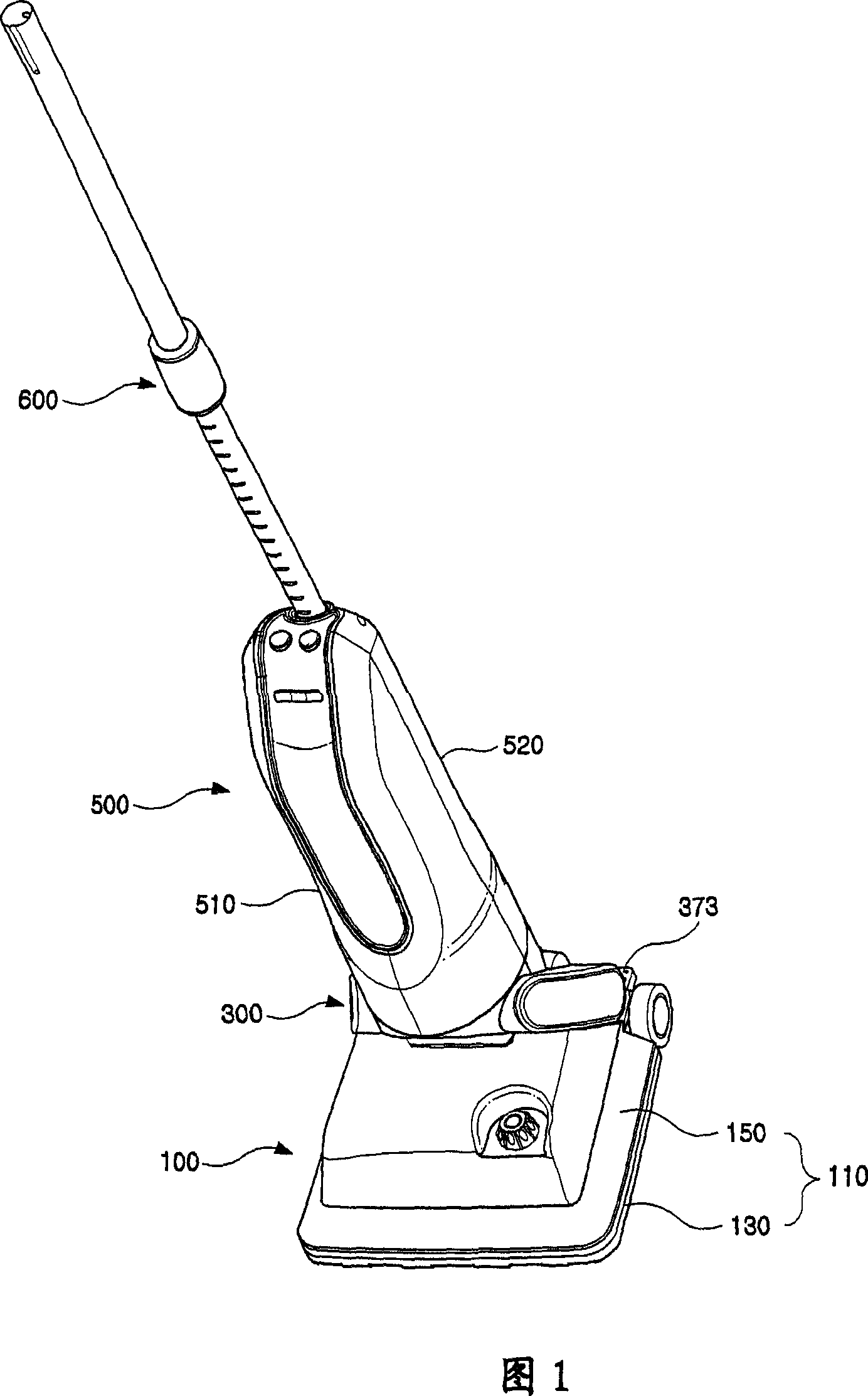
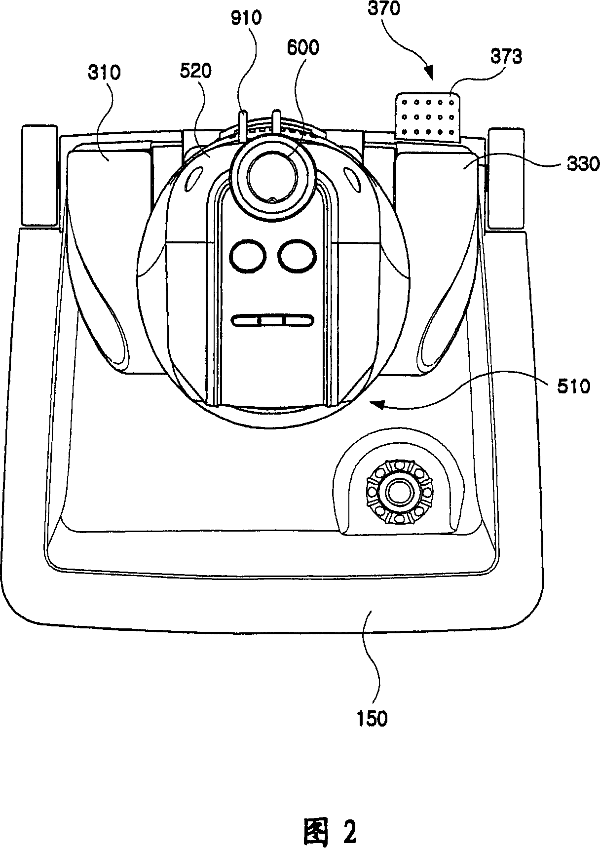
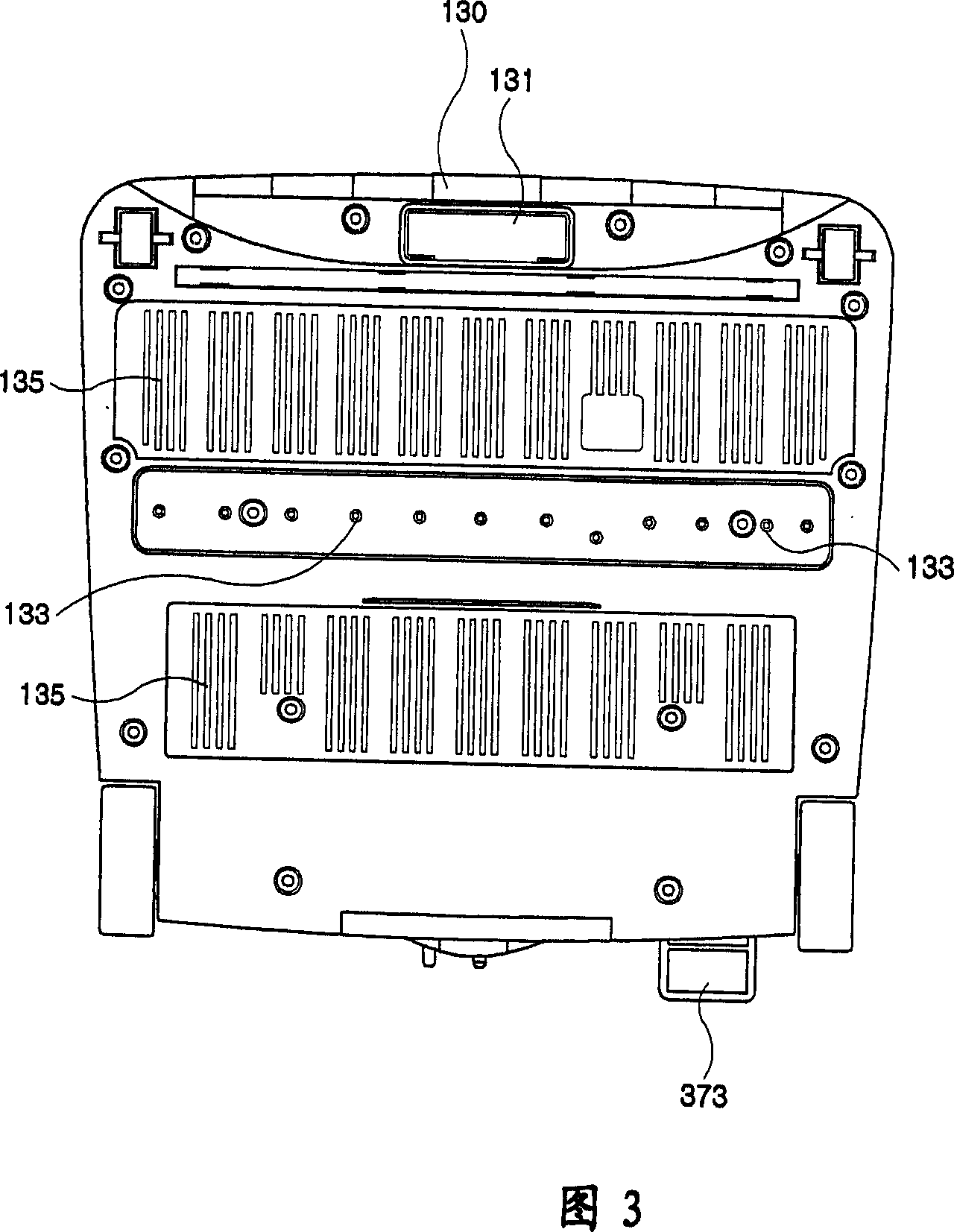
[0081] Fig. 1 is a front perspective view of a steam vacuum cleaner according to an example of the present invention, and Fig. 2 to Fig. 4 are a plan view, a bottom view and a back view of Fig. 1 .

[0082] As shown in Fig. 1 and Fig. 4, the steam vacuum cleaning machine in the present example is made up of base 100, operation main body 500, and neck 300 connecting base 100 and operation main body 500, meanwhile, operation main body There should be a handle bar 600 that can be adjusted in length on the 500, and the handle bar 600 is installed on the pipe 550 to be described in a detachable manner.

[0083] As shown in FIG. 5 , the base 100 is composed of a body 110 composed of a bottom plate 130 and an upper cover 150 , a steam generator 170 mounted on the bottom plate 130 , and a dust box 200 mounted on the back of the body 110 .

[0084] As shown in Figure 4, the b...


PUM


Abstract

A steam type vacuum sweeper comprises a foundation bed connected respectively with a dust arrest box and a vapor generation part, a manipulation body, and a body recess for connecting the manipulation body rotatablely to the foundation bed, wherein said foundation bed is equipped with a suction nozzle and a steam jet hole thereon, the manipulation body is equipped with an electrical machine for intaking air, said body recess includes a first arm and second arm with one end rotatablely connected to the foundation bed and a connection part for connecting the other end of the first arm and second arm, said connection part is also connected with the manipulation body, an air oilchannel intercommunicating pore is provided between the first arm and the connection part. Through such a structure, a dust arrest passage way is constituted at the body recess to simplify the base construction. An electrical machine is mounted at the manipulation body to ensure that the height of the foundation bed will not be affected even if the volume becomes larger when the electrical machine capacity is improved, capable of cleaning-up floor below fleabags, desks and sofas.

Description

technical field [0001] The present invention relates to a cleaning device which utilizes steam sweeping and vacuum suction. Background technique [0002] In the prior art, the vacuum motor of the steam vacuum cleaning machine is installed in the base. When a motor with a large capacity is used to increase the vacuum suction rate, the height of the entire base will rise, making it difficult to clean the underside such as bed boards and sofas; Moreover, the dust collection channel is also arranged in the base, which causes the internal structure of the base to be very complicated. [0003] There is no electric wire reel installed on the existing steam vacuum cleaner, so it is very inconvenient to use the electric wire. [0004] Also, when steam cleaning and vacuum cleaning are performed simultaneously with an existing steam vacuum cleaner, steam is sucked into the motor, causing a short-circuit accident. [0005] The wires for connecting the switc...

Claims


Application Information

Patent Timeline
Patent Type & Authority Applications(China)
IPC IPC(8): A47L7/06A47L5/12A47L11/34A47L9/00
CPCA47L11/26A47L11/4044A47L11/4086A47L11/4088A47L11/4094
Inventor 韩京姬
Owner 韩京姬
Why Eureka
Try Eureka