Method of manufacturing manganese tetrafluoride
A technology of manganese tetrafluoride and fluorinating agent, applied in the direction of manganese halide, etc., can solve the problems of difficult commercial production and low conversion rate of MnF4
- Summary
- Abstract
- Description
- Claims
- Application Information
AI Technical Summary
Problems solved by technology
Method used
Image


Examples
Embodiment 1
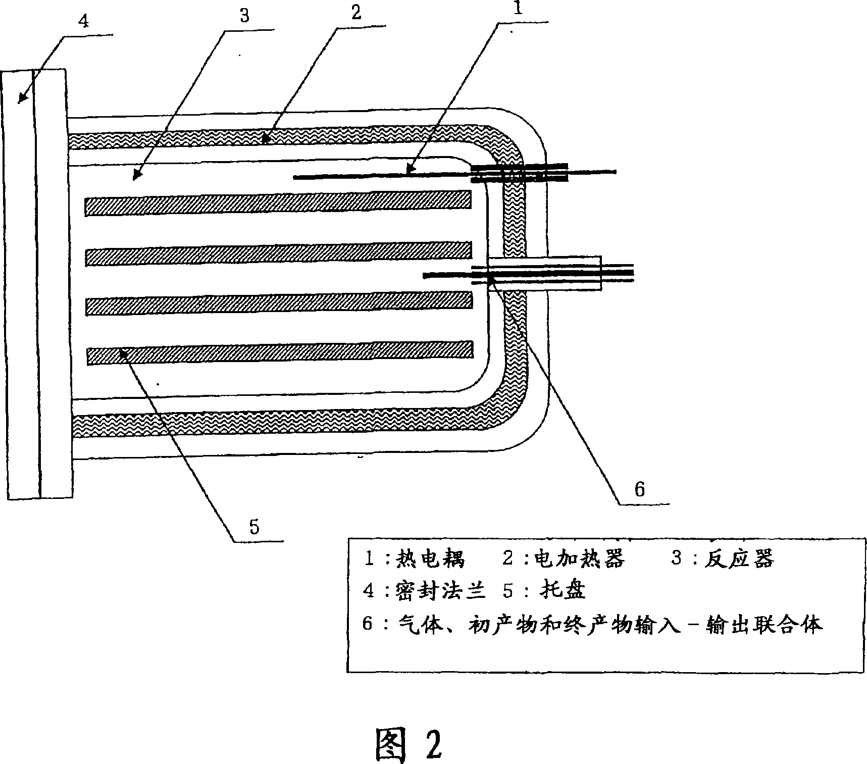
[0036] In the box (6) with controlled dew point, 4500g manganese difluoride (MnF 2 ) placed on the tray ((5) in Figure 2) of the reactor (4) included in the structure of the test device (Figure 1).
[0037] The reactor (4) was evacuated, fluorine gas was fed until the pressure P was 2.0 MPa, and the reactor (4) was kept at a temperature T of 250° C. until the pressure became constant.
[0038] When the pressure P drops below 1.0 MPa, feed fluorine gas into the reactor (4) until the pressure P rises to 2.0 MPa.
[0039] When the pressure P of the reactor (4) is stable, the process is considered as completed.
[0040] After the reactor (4) was evacuated and fed with nitrogen until its pressure reached room pressure, the fluorine-treated product was removed.
[0041] The product was weighed, and the composition of each reaction product was calculated based on the weight gain.
[0042] Next, the reaction product is ground in a bar mill (7) and placed in a reactor (4) where the ...
Embodiment 2-10
[0049] In a box with controlled dew point, 2500g of manganese difluoride (MnF 2 ) into the reactor (4) ((1) in Fig. 4) with a ball mill included in the structure of the test device (Fig. 3).
[0050] The reactor (4) was maintained to have a constant temperature T of 250°C. Evacuate the reactor (4) and feed in fluorine until the pressure P 1 to 2.0MPa and turn it off. The reactor (4) with the ball mill is rotated, and the reaction is carried out while pulverizing and crushing the manganese compound therein.
[0051] Pressure P is detected when necessary 2 When it is lower than 1.0MPa, feed fluorine gas into the reactor (4) until it returns to the pressure P of 2.0MPa 1 , and then turn it off.
[0052] When the pressure P of the reactor (4) is stable, the process is considered as completed.
[0053] After the reactor (4) was evacuated and fed with nitrogen until its pressure reached room pressure, the fluorine-treated product was removed.
[0054] The product was weighed,...
Embodiment 11-14
[0061] In a box with a controlled dew point, 2500 g of manganese fluoride monohydrate (MnF 2 ·H 2 O) Loading into the reactor (4) ((1) in Fig. 4) with ball mill included in the structure of the test apparatus (Fig. 3).
[0062] Evacuate the reactor (4) and feed in fluorine until the pressure P 1 is 6.0MPa, close it. The reactor with the ball mill was rotated, the reaction was carried out while pulverizing and crushing the manganese compound therein, and the heater was turned on so that the reactor (4) had a constant temperature T of 300°C.
[0063] Pressure P is detected when necessary 2 When it is lower than 5.0MPa, feed fluorine gas into the reactor (4) until it returns to the pressure P of 6.0MPa 1 , and then turn it off.
[0064] When the pressure P of the reactor (4) is stable, the process is considered as completed.
[0065] After the reactor (4) was evacuated and fed with nitrogen until its pressure reached room pressure, the fluorine-treated product was removed. ...
PUM
 Abstract
Description
Claims
Application Information
 - R&D
- Intellectual Property
- Life Sciences
- Materials
- Tech Scout
- Unparalleled Data Quality
- Higher Quality Content
- 60% Fewer Hallucinations
Browse by: Latest US Patents, China's latest patents, Technical Efficacy Thesaurus, Application Domain, Technology Topic, Popular Technical Reports.
© 2025 PatSnap. All rights reserved.Legal|Privacy policy|Modern Slavery Act Transparency Statement|Sitemap|About US| Contact US: help@patsnap.com