
Heating cooker

A technology for cookers and heating chambers, which is applied to electric heating fuels, steam cooking utensils, lighting and heating equipment, etc., can solve problems such as increased cost, unsuitability for household microwave ovens, and narrow irradiation range of laser monomers, and achieves prevention of delicious ingredients. The effect of reducing and preventing the reduction of delicious ingredients

Inactive Publication Date: 2007-08-29
HITACHI APPLIANCES INC
View PDF2 Cites 11 Cited by
  • Summary
  • Abstract
  • Description
  • Claims
  • Application Information

AI Technical Summary

Problems solved by technology

[0022] Furthermore, as shown in Patent Document 2, in the method of decomposing protein in the object to be heated by irradiating high-energy laser light, it is difficult to use household power output to promote protein decomposition because the power that can be used in a household microwave oven is limited. high energy light
[0023] In addition, since the irradiation range of the single laser is narrow, in order to widely act on the surface of the object to be heated, it can be considered to make the exit of the laser movable, or to increase the number of lasers, but any solution will increase the cost and is not suitable for household microwave oven
[0024] In addition, when the object to be heated is irradiated with high energy and the temperature rises sharply, the temperature band that increases the delicious ingredients in the object to be heated passes quickly, so there is no factor to increase the delicious ingredients other than the protein decomposed by the laser

Method used


Image

  • Heating cooker
  • Heating cooker
  • Heating cooker

Examples


Embodiment 2

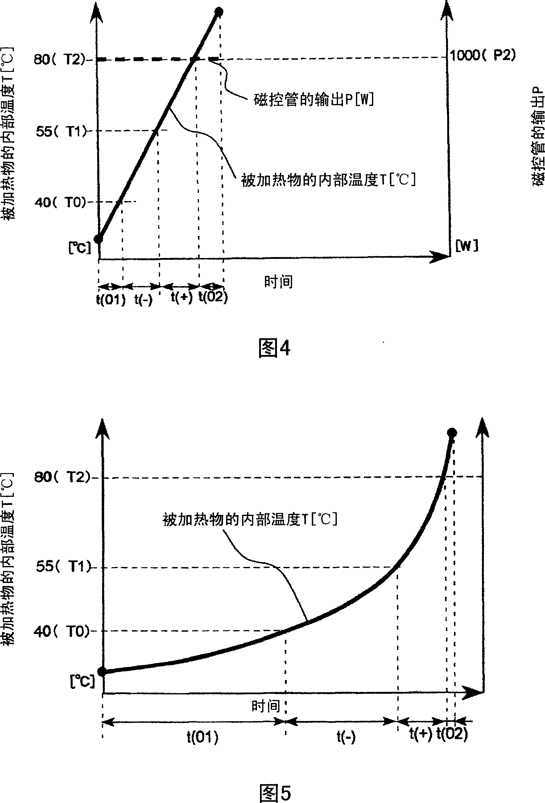
[0127] Fig. 6 shows the temporal change of the internal temperature of the object to be heated and the heating pattern during heating and cooking in the microwave oven according to the second embodiment of the present invention.

[0128] The heating and cooking mode of the microwave oven 1 of the present invention is as follows: at the beginning of heating, a combination of low-output microwave heating and low-output oven heating is performed, then high-output microwave heating is performed, and then low-output oven heating and low-output oven heating are combined. Steam heating for heating and finally grilling for heating.

[0129] Here, each heating mode is described in detail.

[0130] First, cooking is performed by combining microwave heating with low output (350W) and oven heating with low output (650W) until the internal temperature of the object reaches T0.

[0131] Since the temperature of the heating chamber is low at the beginning of heating, the ability to heat the...

Embodiment 5

[0167] Fig. 9 is a structural diagram of a microwave oven according to a fifth embodiment of the present invention seen from the front.

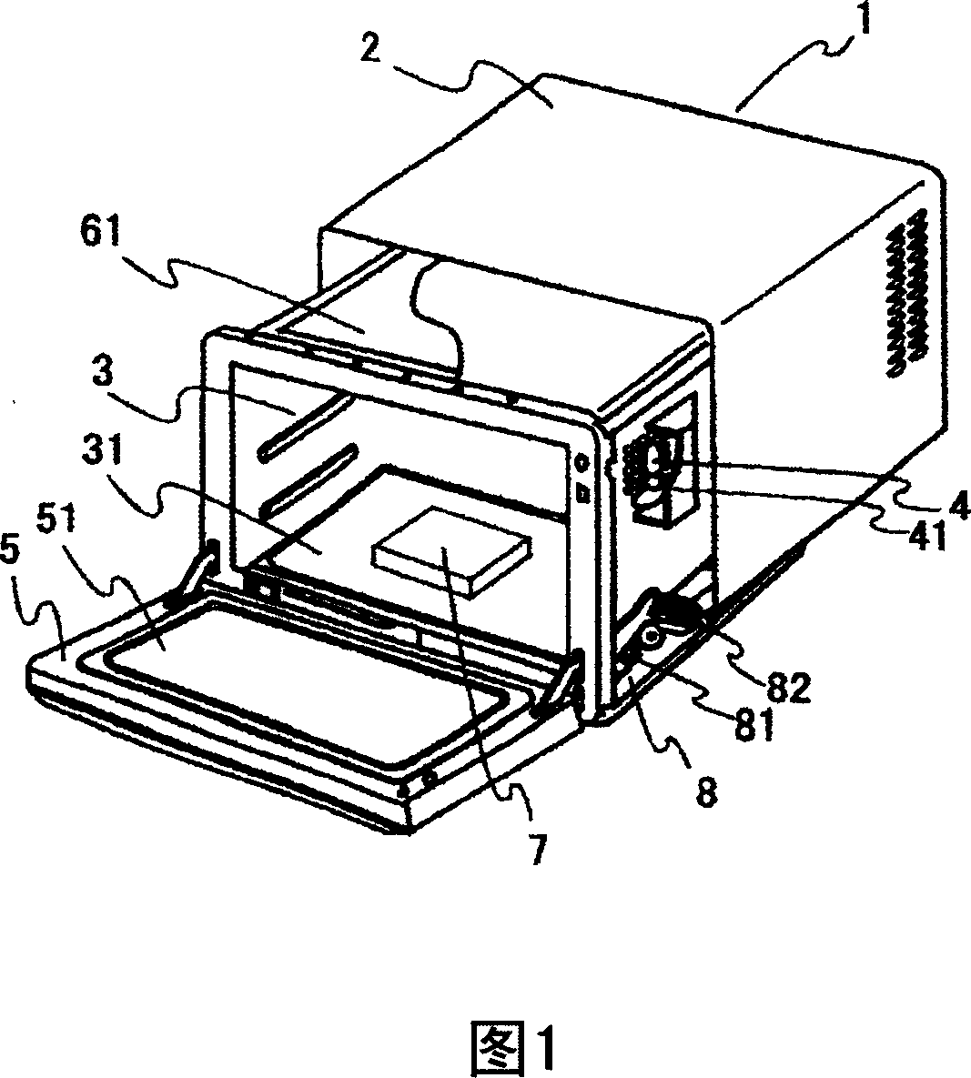
[0168] The present microwave oven 1 has a structure in which a heating chamber 3 and a machine chamber (not shown) on the heating chamber side are surrounded by a casing 2 .

[0169] The object to be heated 7 is placed on the workbench 31 arranged at the lower part of the heating chamber 3 and then heated and cooked.

[0170] The magnetron arranged in the mechanical room, the upper heater arranged above the heating chamber 3, and the hot air heater (any one of which is not shown) arranged at the rear of the heating chamber are heating mechanisms. The heating and cooking of the object to be heated 7 on the 31.

[0171] Here, a temperature sensor 91 is arranged on the side of the heating chamber 3, and a temperature estimation mechanism (not shown) is arranged in the machine room. The surface temperature of the object 7 to be heated is measur...


PUM


Abstract

The present invention relates to a heating cooker which can execute the heating cook the heated object with added delicious components. During the temperature elevating process for the internal temperature of the heated object, the temperature that the enzyme for decomposing the delicious components in the heated object begins to activate is set to (T0); the temperature that the enzyme for decomposing the delicious components in the heated object begins to inactivate is set to (T1); the temperature that the enzyme for decomposing the protein of the heated object and generating the delicious components begins to inactivate is set to (T2). During the time t (01) in the range (T F24C 7 / 08 F24C 7 / 02 A47J 27 / 04 7 18 2 2007 / 1 / 22 101025275 2007 / 8 / 29 000000000 Hitachi Air Conditioning & Home Electrical Appliance Co., Ltd. Japan Tanaka Sachi Tategawa Akirayuki Otsu Noriyuki Hanasaka Teruhiko Honma Mitsu Seibori Akiko zhangjing qiang 11243 Japan 2006 / 2 / 20 2006-041789

Description

technical field [0001] The present invention relates to heating cookers such as microwave ovens. Background technique [0002] Conventionally, in heating cookers such as household microwave ovens, the output during heating has been adjusted in order to perform heating and cooking more quickly and more uniformly. [0003] For example, when cooking stir-fried vegetables that need to be cooked with strong heat, in order to cook with limited power in a short time, heat cooking is performed by irradiating the microwave with the highest output for a certain period of time. [0004] In addition, when it is desired to have a grilled color on the surface of the object to be heated, in order to make the air in the heating chamber a uniform temperature, while heating the air with a heater with a certain output, a fan is used to stir the air in the heating chamber with hot air. Hot air cooking, which enables uniform heating and cooking. [0005] On the other hand, studies have been ma...

Claims


Application Information

Patent Timeline
Patent Type & Authority Applications(China)
IPC IPC(8): F24C7/08F24C7/02A47J27/04
Inventor 田中佐知立川晃之大都纪之花坂照彦本间满青堀明子
Owner HITACHI APPLIANCES INC
Learn More