Vertical life refuse heat decomposition incinerator
A domestic garbage and incinerator technology, applied in the field of incinerators, can solve the problems of low water seal of the slag extractor, insufficient use of waste heat, unstable combustion, etc., and achieve the effects of low failure rate, improved site environment, and small maintenance
- Summary
- Abstract
- Description
- Claims
- Application Information
AI Technical Summary
Problems solved by technology
Method used
Image
Examples
Embodiment 1
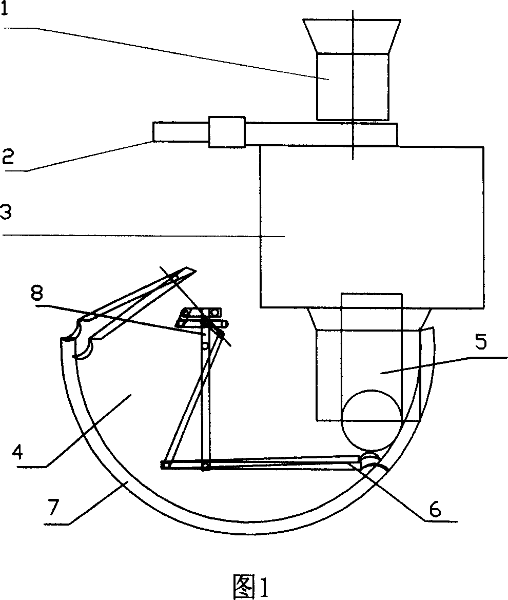
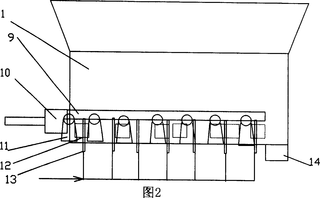
[0024] Embodiment 1 In Figs. 1 and 2, a vertical domestic waste thermal decomposition incinerator includes an incinerator body 3, a hopper and a feeding bin 1 at the front end of the incinerator body 3, and a slagging device 4 at the rear end; its features In that: a stepping feeding device 2 is provided at the front end of the hopper and feeding bin 1; the feeding device 2 is a stepping conveyor, mainly including a conical hopper, a trough, a horizontal stepping plate 12, a hydraulic drive device 10 and a hot air Composed of drying chamber 13; the top of horizontal stepping plate 12 is connected with conical hopper 1, and the bottom is provided with hot air drying chamber 13; horizontal stepping plate 12 is connected with push rod mechanism 9 on roller bracket 11 and driven by hydraulic drive device 10, The rubbish is pushed into the discharge port 14 in a step-by-step manner. In view of the problem that the 100t / d vertical thermal decomposition furnace that has been put into...
Embodiment 2
[0026] Example 2 A vertical domestic waste thermal decomposition incinerator, in which the hot air drying chamber 13 is connected to the flue gas air preheater in the tail flue of the boiler body of the incinerator body, and the hot air for drying is introduced. All the other are with embodiment 1. The waste heat of the flue gas is used to heat the cold air, and the heated hot air is supplied to the walking garbage conveyor. Hot air can be used as its backup hot air source. Using the waste heat of the flue gas can reduce the exhaust gas temperature and improve the efficiency of the boiler.
Embodiment 3
[0027] Example 3 A vertical domestic waste thermal decomposition incinerator, wherein the slag removal device 4 adopts a hydraulic bucket arm type slag discharger; its structure is that the bottom of the air inlet pipe 5 is water-sealed at the bottom of the tank 7 below the outlet of the ash hopper A dust-scraping board 6 is set, and the dust-scraping board 6 is driven by a bucket arm type connecting rod transmission mechanism 8 . As shown in Figure 1. General waste incineration devices such as grate furnaces and circulating fluidized bed furnaces use hydraulic arc-shaped push plate slag machines or chain plate slag machines. Because the vertical rotary pyrolysis waste incinerator has a conical ash hopper at the lower part of the furnace body inserted into the water seal tank, and the primary air pipe of the first combustion chamber passes through the center of the conical ash hopper and then enters the air under the rotary grate. chamber, the slag falls into the water from t...
PUM
 Abstract
Description
Claims
Application Information
 - R&D Engineer
- R&D Manager
- IP Professional
- Industry Leading Data Capabilities
- Powerful AI technology
- Patent DNA Extraction
Browse by: Latest US Patents, China's latest patents, Technical Efficacy Thesaurus, Application Domain, Technology Topic, Popular Technical Reports.
© 2024 PatSnap. All rights reserved.Legal|Privacy policy|Modern Slavery Act Transparency Statement|Sitemap|About US| Contact US: help@patsnap.com


