Ablation-resistant pipe joint
A technology of anti-erosion and pipe joints, applied in the field of pipe joints, can solve the problems of hours or even hours, waste of resources, environment, impact on production, etc., and achieve the effect of reducing losses, prolonging service life, and reducing impact
- Summary
- Abstract
- Description
- Claims
- Application Information
AI Technical Summary
Problems solved by technology
Method used
Image

Examples
Embodiment I
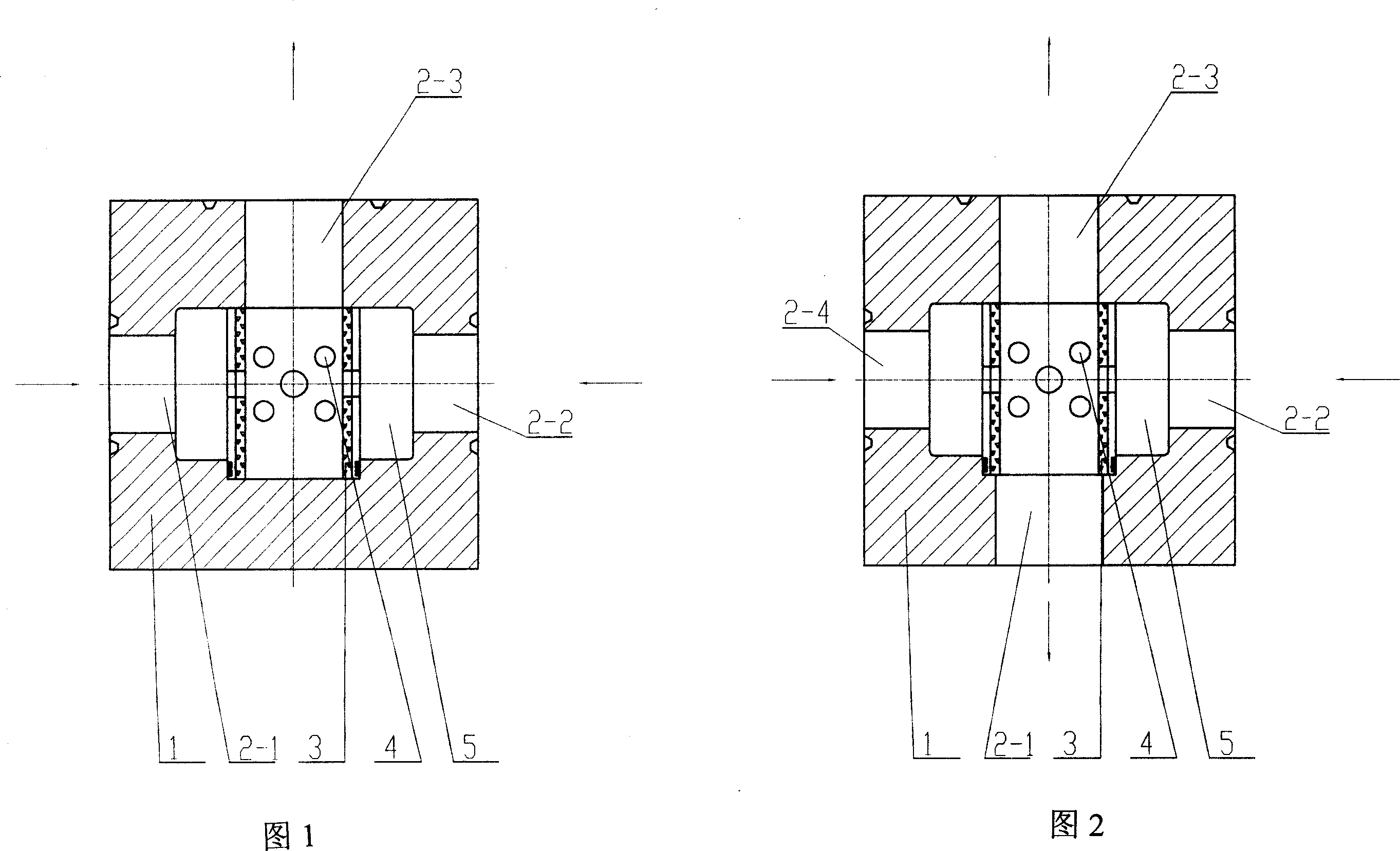
[0019] Embodiment 1, as shown in Figure 1: offer three through holes 2-1, 2-2, 2-3 on the pipe joint body 1 that is made of 35CrMo (or 25CrNiMoE) alloy steel, constitute three-way pipe joint (commonly known as is a tee), and the three through holes 2-1, 2-2, 2-3 are distributed in a T shape; at the confluence of the three through holes 2-1, 2-2, 2-3 in the inner cavity of the body 1, there is a The working medium buffer cavity 5 is provided with a screen tube 3 made of hard alloy GY8, the axis of the screen tube 3 is perpendicular to the through holes 2-1 and 2-2 where the working medium enters, and the screen tube Several screen holes 4 are opened on the side wall of 3; and the inner diameter of the screen pipe 3 is the same as that of the through hole 2-3.
[0020] When in use, when the high-speed, high-pressure working medium enters the body 1 from the through holes 2-1, 2-2 (or one of them) through the screen hole 4, it is buffered in the cavity 5 and forms a flow directio...
Embodiment II
[0022] Embodiment II, as shown in Figure 2: the pipe joint body 1 made of 35CrMo alloy steel is provided with four through holes 2-1, 2-2, 2-3, 2-4, forming a four-way pipe joint, The four through holes 2-1, 2-2, 2-3, 2-4 are distributed in a cross shape. At the confluence of the four through holes 2-1, 2-2, 2-3, and 2-4 in the inner cavity of the body 1, there is a cavity 5 for buffering the working medium, and the cavity 5 is made of hard alloy GY8. The screen tube 3, the axis of the screen tube 3 is perpendicular to the through holes 2-2, 2-4 where the working medium enters, and several screen holes 4 are opened on the side wall of the screen tube 3; -1, 2-3 have the same inner diameter.
[0023] When in use, when the high-speed, high-pressure working medium enters the body 1 from the through holes 2-4, 2-2 (or one of them), it flows out from the other through holes.
[0024] If the working medium enters through the through holes 2-1, 2-3 (or one of them), the screen tube...
Embodiment III
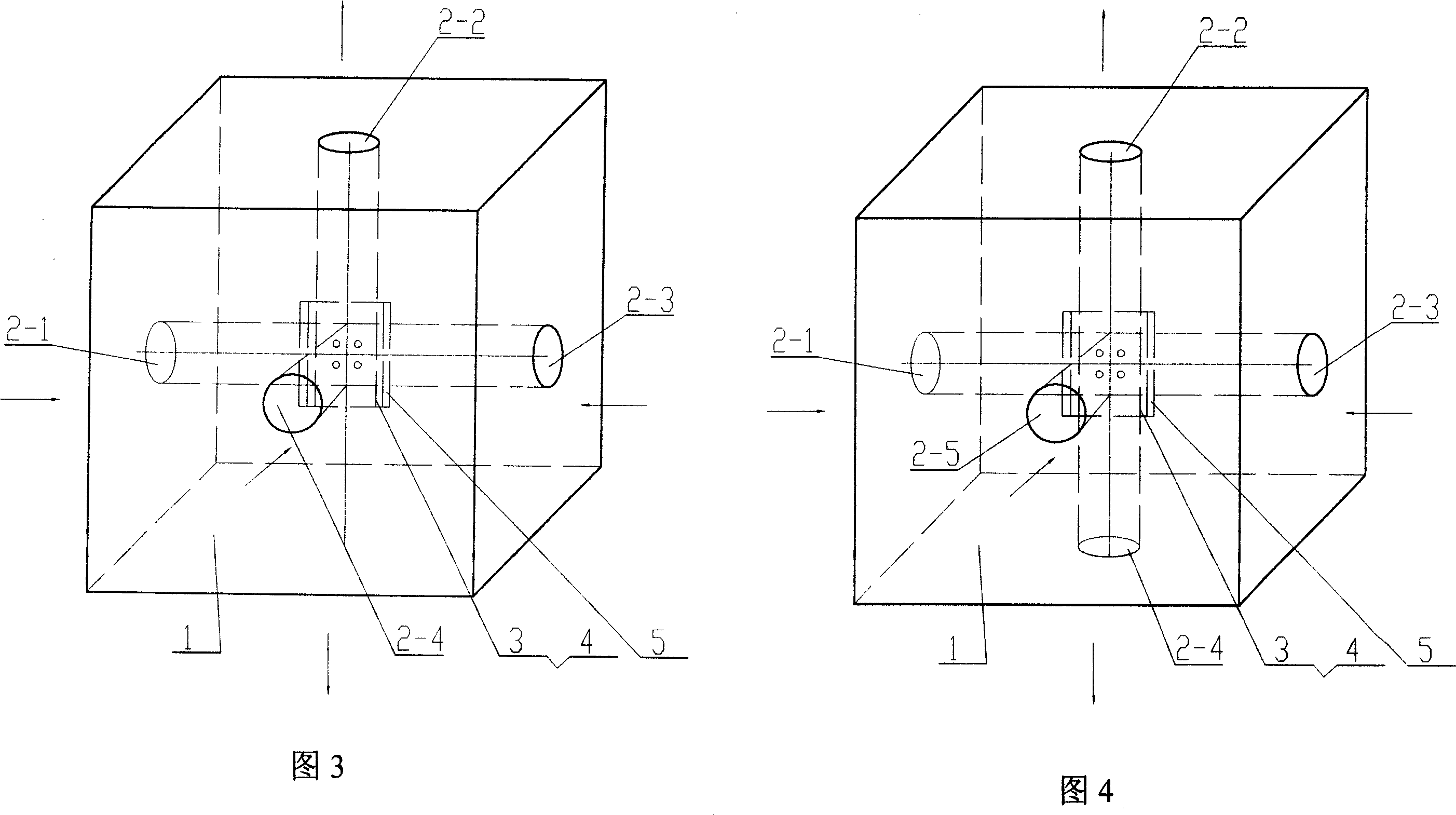
[0025] Embodiment III, as shown in Figure 3: the pipe joint body 1 made of 25CrNiMoE alloy steel is provided with four through holes 2-1, 2-2, 2-3, 2-4 to form a four-way pipe joint, Three of the through holes 2-1, 2-3, 2-4 are on the same horizontal plane and are T-shaped, and the fourth through hole 2-2 is located in the three through holes 2-1, 2-3, 2-4 On the vertical plane of the confluence, and perpendicular to the above-mentioned three through holes 2-1, 2-3, 2-4; four through holes 2-1, 2-2, 2-3, 2-4 in the body The confluence is provided with a cavity 5 for working medium buffering, and a screen tube 3 made of cemented carbide GY8 is provided in the cavity 5, and the axis of the screen tube 3 is connected with the through holes 2-1 and 2-3 where the working medium enters , 2-4 are perpendicular to each other, and several screen holes 4 are opened on the side wall of the screen pipe 3 .
[0026] When in use, when the high-speed, high-pressure working medium enters the...
PUM
 Abstract
Description
Claims
Application Information
 - R&D
- Intellectual Property
- Life Sciences
- Materials
- Tech Scout
- Unparalleled Data Quality
- Higher Quality Content
- 60% Fewer Hallucinations
Browse by: Latest US Patents, China's latest patents, Technical Efficacy Thesaurus, Application Domain, Technology Topic, Popular Technical Reports.
© 2025 PatSnap. All rights reserved.Legal|Privacy policy|Modern Slavery Act Transparency Statement|Sitemap|About US| Contact US: help@patsnap.com