Rotor position presuming method and apparatus, motor control method and compressor

A technology of rotor position and control method, which is used in electronic commutation motor control, motor generator control, AC motor control and other directions to achieve the effects of improving position estimation accuracy, easy design, and good stability characteristics

Active Publication Date: 2010-01-20
FUJITSU GENERAL LTD
View PDF3 Cites 0 Cited by
  • Summary
  • Abstract
  • Description
  • Claims
  • Application Information

AI Technical Summary

Problems solved by technology

The rectangular wave sensorless control method is a method of detecting induced voltage, although it has been established technically, this method is limited to rectangular wave driving in which the driving waveform is centered on 120° driving

Method used


Image

  • Rotor position presuming method and apparatus, motor control method and compressor
  • Rotor position presuming method and apparatus, motor control method and compressor
  • Rotor position presuming method and apparatus, motor control method and compressor

Examples


Embodiment Construction

[0085] Hereinafter, an embodiment of the rotor position estimation method of the present application will be described in detail with reference to the drawings.

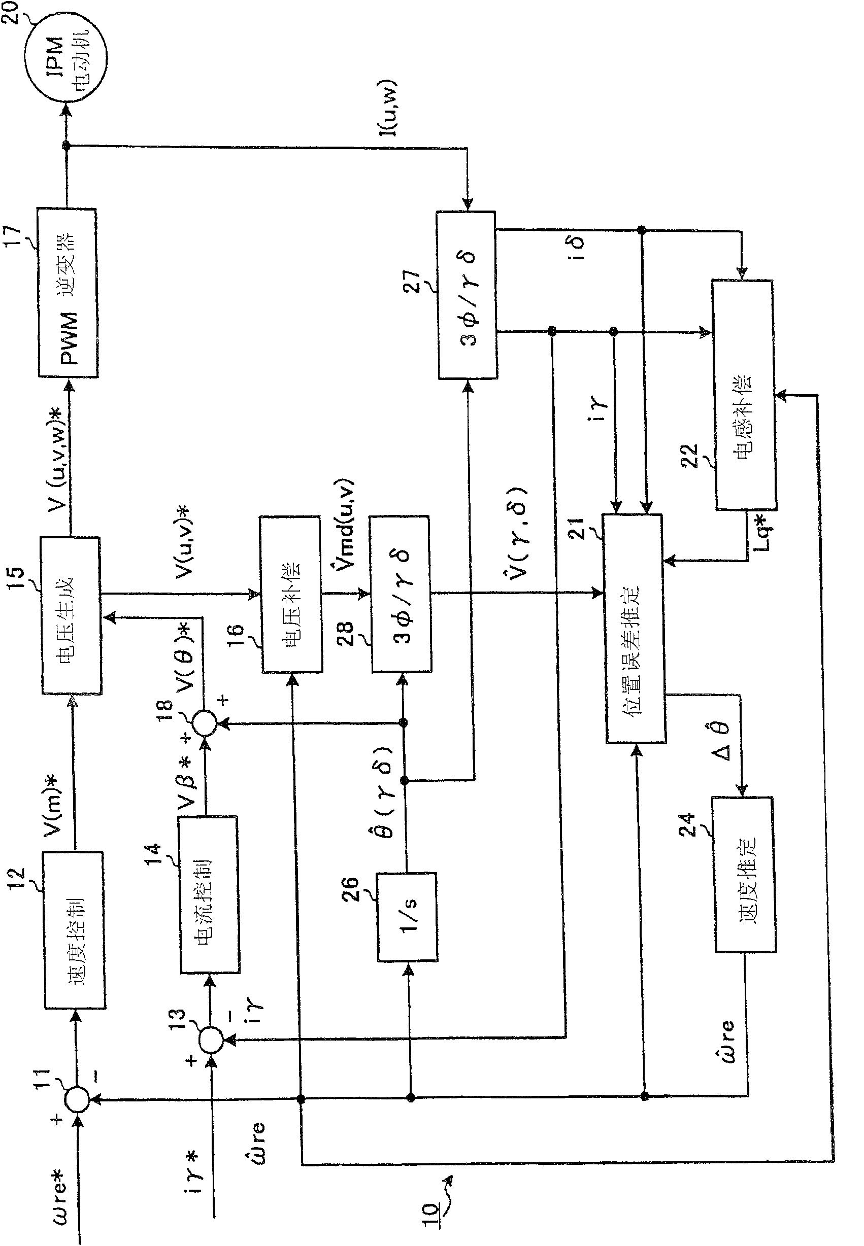
[0086] This implementation forms a 180° sine wave sensorless control technology involving permanent magnet motors (DC brushless motors, IPM motors) with salient poles. Such as Image 6 As shown, in the 180° sine wave sensorless control, the d-q axis actual rotating coordinate system composed of the position in the direction of the permanent magnet rotor flux, that is, the d-axis and the q-axis that is 90° ahead of the d-axis in the direction of rotation, and the control The axis offset Δθ between the virtual rotor position γ-axis on the γ-axis and the γ-δ axis formed from the γ-axis ahead of the δ-axis in the direction of rotation by 90° is controlled to be zero.

[0087] Since the angle θ of the rotor (rotor position) is an integral value of the angular velocity ω of the rotor, when the position offset (Δθ) is cont...


PUM


Abstract

The invention provided a rotor position estimating method for easily designing a controller and easily obtaining stability. The rotor position estimating method, for estimating a rotor position [theta] of a permanent magnet motor 20, finds a magnetic flux error between a rotational coordinate axis and its estimated axis, and estimates the rotor position based on the magnetic flux error. The magnetic flux error is preferably the magnetic flux error between a q-axis as the rotational coordinate axis and a [delta]-axis as its estimated axis. A magnetic flux comprises an integration of a difference of a voltage drop Ri[gamma] in a current from a voltage V[gamma] applied to the motor. A magnetic flux [phi][delta] comprises a product of an inductance Lq of a motor winding and a current i[delta]. The magnetic flux error is found by estimating the magnetic fluxes. The magnetic flux error between the rotational coordinate axis and its estimated axis is found on the basis of a magnetic flux equation formed by dividing a voltage equation of the permanent magnet motor by an angular speed [omega] of the rotor. The rotor position is estimated on the basis of the magnetic flux error.

Description

technical field [0001] The present invention relates to a method and device for estimating the rotor position of a permanent magnet motor, a method for controlling the motor, a compressor, and a program. Background technique [0002] In permanent magnet motors with salient poles (DC brushless motors, IPM motors), the rotor position can be calculated according to the voltage and current signals obtained from the drive inverter side, and the motor is controlled without physical position sensors and speed sensors. That is, the so-called sensorless control technology is adopted. [0003] As the sensorless control method, there are known a rectangular wave sensorless control method and a sine wave sensorless control method. The rectangular wave sensorless control method is a method of detecting induced voltage, and although it is technically established, this method is limited to rectangular wave driving in which the driving waveform is centered on 120° driving. [0004] At pre...

Claims


Application Information

Patent Timeline
Patent Type & Authority Patents(China)
IPC IPC(8): H02P6/18H02P21/00H02P6/06H02P6/08H02P6/16H02P6/17H02P6/182H02P6/185H02P6/28H02P21/06H02P21/09H02P21/10H02P21/13H02P21/18H02P21/22H02P21/24H02P21/26H02P23/16H02P25/026H02P27/04H02P27/08
CPCB62J1/165B62K19/40
Inventor 村上正宪
Owner FUJITSU GENERAL LTD
Why Eureka
Try Eureka