Apparatus for grinding friction material of brake pad
A friction material and grinding device technology, which is applied in the direction of grinding machines, grinding workpiece supports, grinding/polishing equipment, etc., can solve the problems of negative impact on the initial performance of friction material 3 and reduce the quality of brake pads, etc.
- Summary
- Abstract
- Description
- Claims
- Application Information
AI Technical Summary
Problems solved by technology
Method used
Image
Examples
no. 1 example
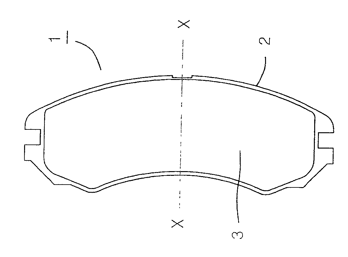
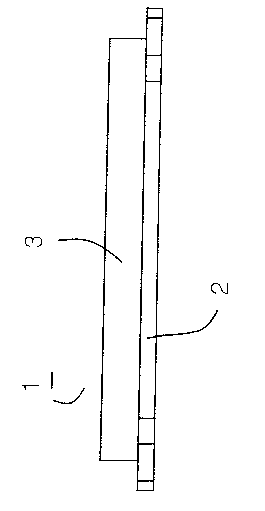
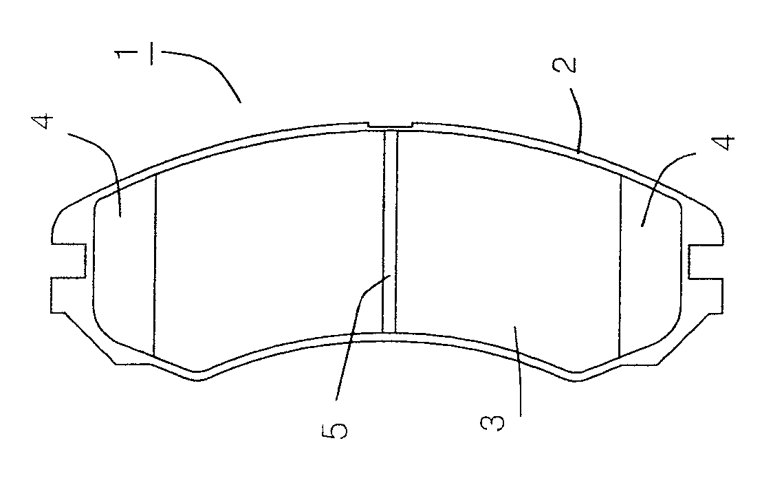
[0054] Figure 11 show as Figures 1 to 4 The shown blank material of the brake pad 1 is in each stage from supply to assembly of the damper spacer.
[0055] Such as Figure 11 As shown, the brake pad friction material grinding device of the present invention includes a supply part 30 for supplying blank material for brake pads; a first grinding part 34 composed of a rough grinding part 32; a groove processing part 36; an inclined surface processing part 38; a fine grinding part The second grinding part 42 composed of 40; the coating part 44 for coating the surface of the support plate; the scorching treatment part 46 for scorching the surface of the friction material; The third grinding part 50 composed of the secondary fine grinding part 48 of the surface of the secondary fine grinding process; the marking (marking) part 52 of manufacturer information and product serial number etc. on the surface of the support plate; A shim assembly part 54 of a damping shim.
[0056] ...
no. 2 example
[0078] The second embodiment will combine the attached Figures 18 to 20 to explain, and if Figure 4 As shown, in order to process and form the inclined groove 5' on the friction material 3 of the brake pad 1, some functions are added or modified on the basis of the first embodiment.
[0079] As described in the context of the first embodiment, from the supply part 30 to the coarse grinding part 32, the brake pad setting groove 58 of the transfer plate 60 is transferred in a state where the central axis X-X of the brake pad 1 is aligned. In addition, since the groove processing part 36 is provided with the groove molar 64 whose central axis is at right angles to the advancing direction of the machine table 56, the brake pad 1 transferred to the above groove processing part 36 needs to be made of the friction material 3 In the upward state, the central axis X-X moves at a certain angle with respect to the traveling direction of the machine table 56 .
[0080] Such as Figur...
no. 3 example
[0087] The third embodiment will combine the attached Figures 21 to 24 to explain, and if Figure 23 and 24 As shown, on the basis of the first embodiment, components for removing the inner edge 106 of the friction material 3 of the brake pad 1 are added or deformed for this purpose.
[0088] Here, the "inner edge" of the friction material 3 refers to the friction material 3 that acts on the friction surface of the brake disc, and is formed according to the form of the brake disc. The edge of the central axis of the disk.
[0089] Such as Figure 23 and 24 , the inner edge 106 of the friction material 3 of the brake pad 1 is removed. The inner edge 106 is ground and removed in a straight line along the long axis of the brake pad 1 . Such as Figure 21 and 22 As shown, an inner edge removal processing portion 108 as a grinding removal inner edge 106 is provided between the supply portion 30 and the rough grinding portion 32 . The above-mentioned inside edge removal pr...
PUM
 Abstract
Description
Claims
Application Information
 - R&D
- Intellectual Property
- Life Sciences
- Materials
- Tech Scout
- Unparalleled Data Quality
- Higher Quality Content
- 60% Fewer Hallucinations
Browse by: Latest US Patents, China's latest patents, Technical Efficacy Thesaurus, Application Domain, Technology Topic, Popular Technical Reports.
© 2025 PatSnap. All rights reserved.Legal|Privacy policy|Modern Slavery Act Transparency Statement|Sitemap|About US| Contact US: help@patsnap.com


