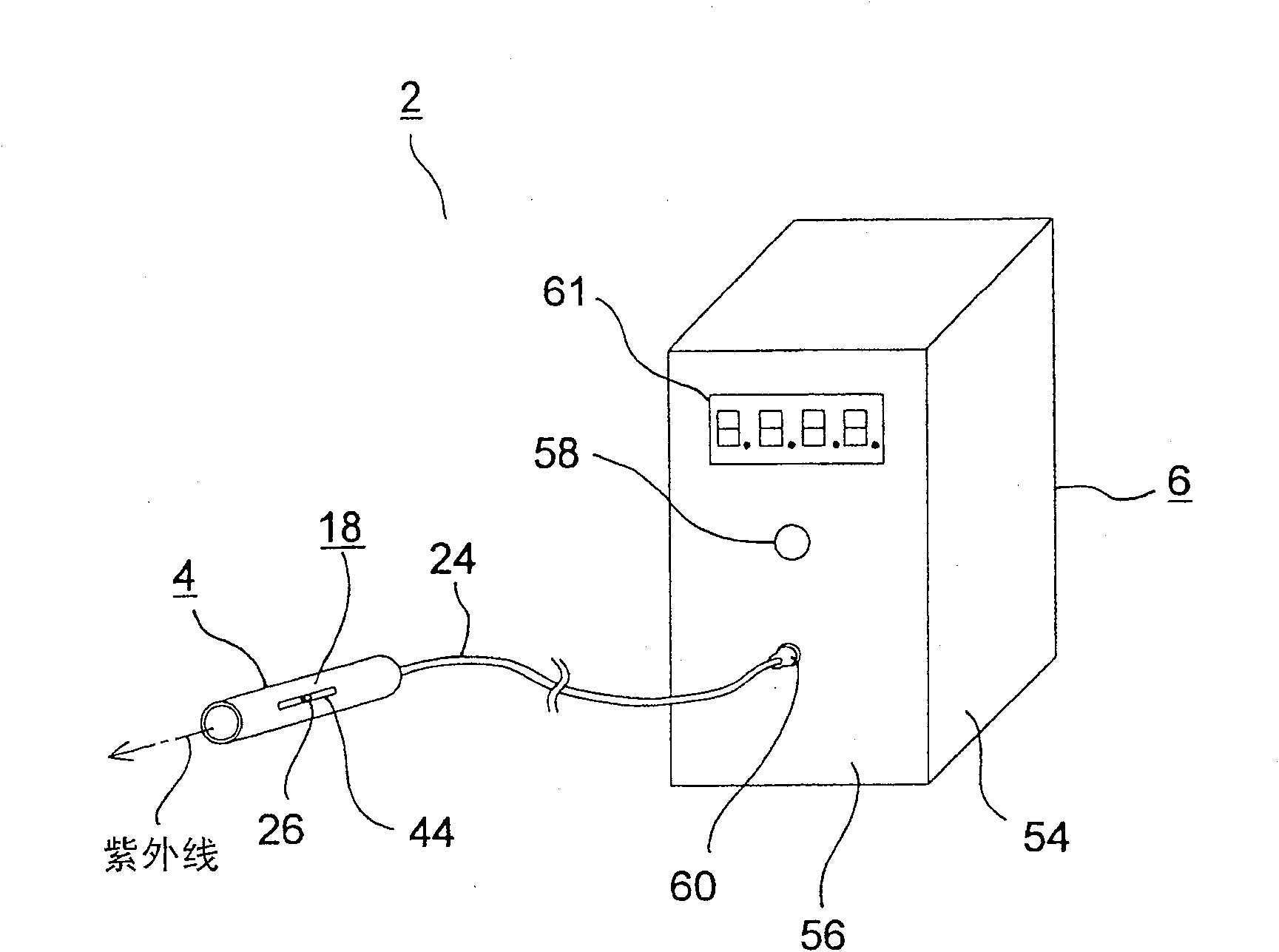
Ultraviolet ray radiating device
A technology of irradiation device and ultraviolet rays, which is applied in the direction of irradiation devices, installations, instruments, etc., can solve the problems of inability to irradiate, increase the cost of ultraviolet irradiation devices, etc., and achieve the effect of easy focus
- Summary
- Abstract
- Description
- Claims
- Application Information
AI Technical Summary
Problems solved by technology
Method used
Image
Examples
no. 1 approach
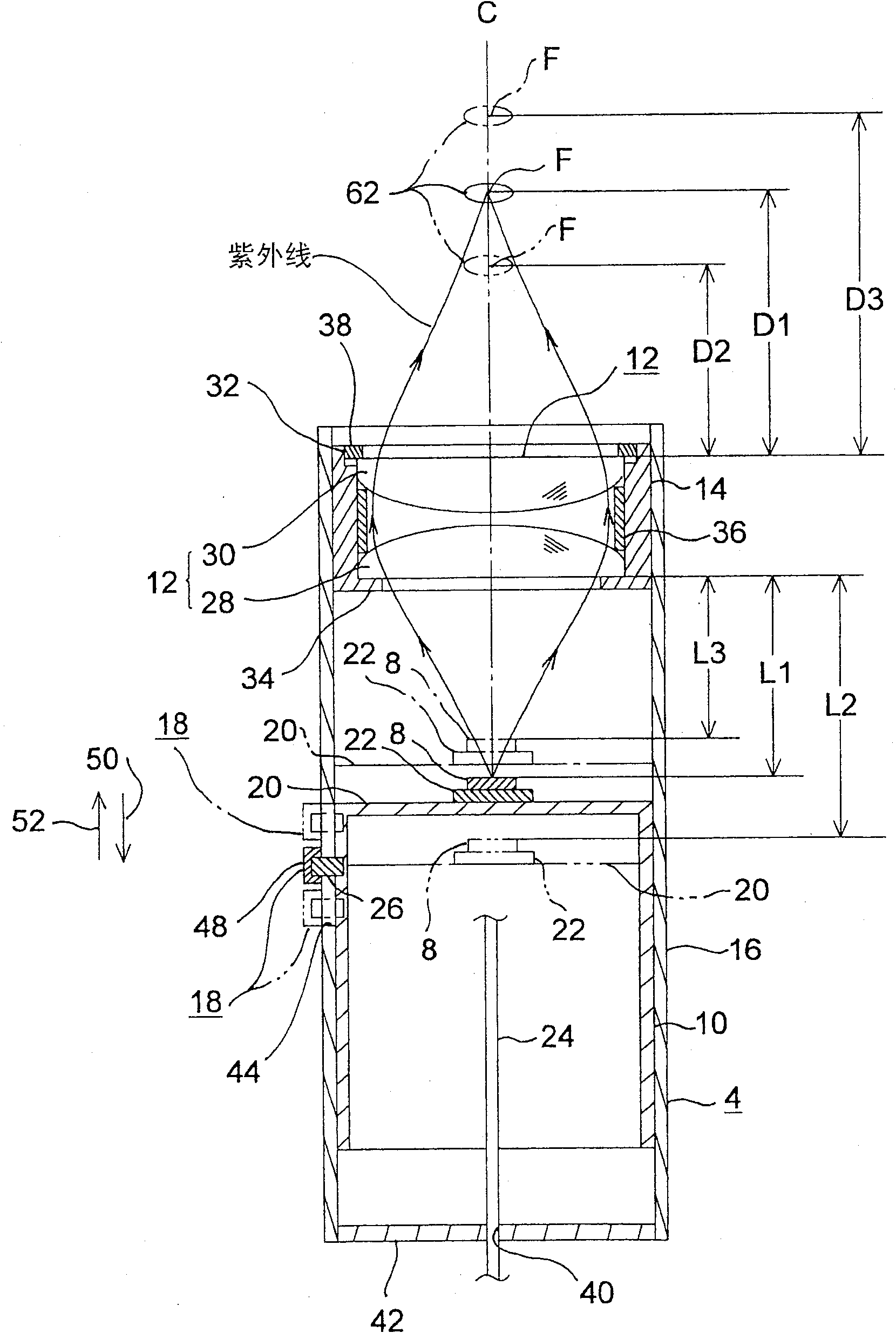
[0041] First, refer to figure 2 The head of the first embodiment of the present invention will be described. figure 2 It is a schematic cross-sectional view showing the head portion according to the first embodiment of the present invention.
[0042] refer to figure 2 , the illustrated head 4 has: a light-emitting diode 8 for irradiating ultraviolet rays; a first mounting mechanism 10 such as a cylinder for installing the light-emitting diode 8; a condenser lens 12 for converging the ultraviolet rays irradiated from the light-emitting diode 8; The second installation mechanism 14 of cylindrical shape etc. that installs condenser lens 12; The cylindrical outer casing 16 that is used to support the first installation mechanism 10 and the cylindrical shape of second installation mechanism 14; For adjusting light emitting diode 8 and A separation distance adjustment mechanism 18 for the separation distance of the condenser lenses 12 .
[0043] The light emitting diode 8 is c...
no. 2 approach
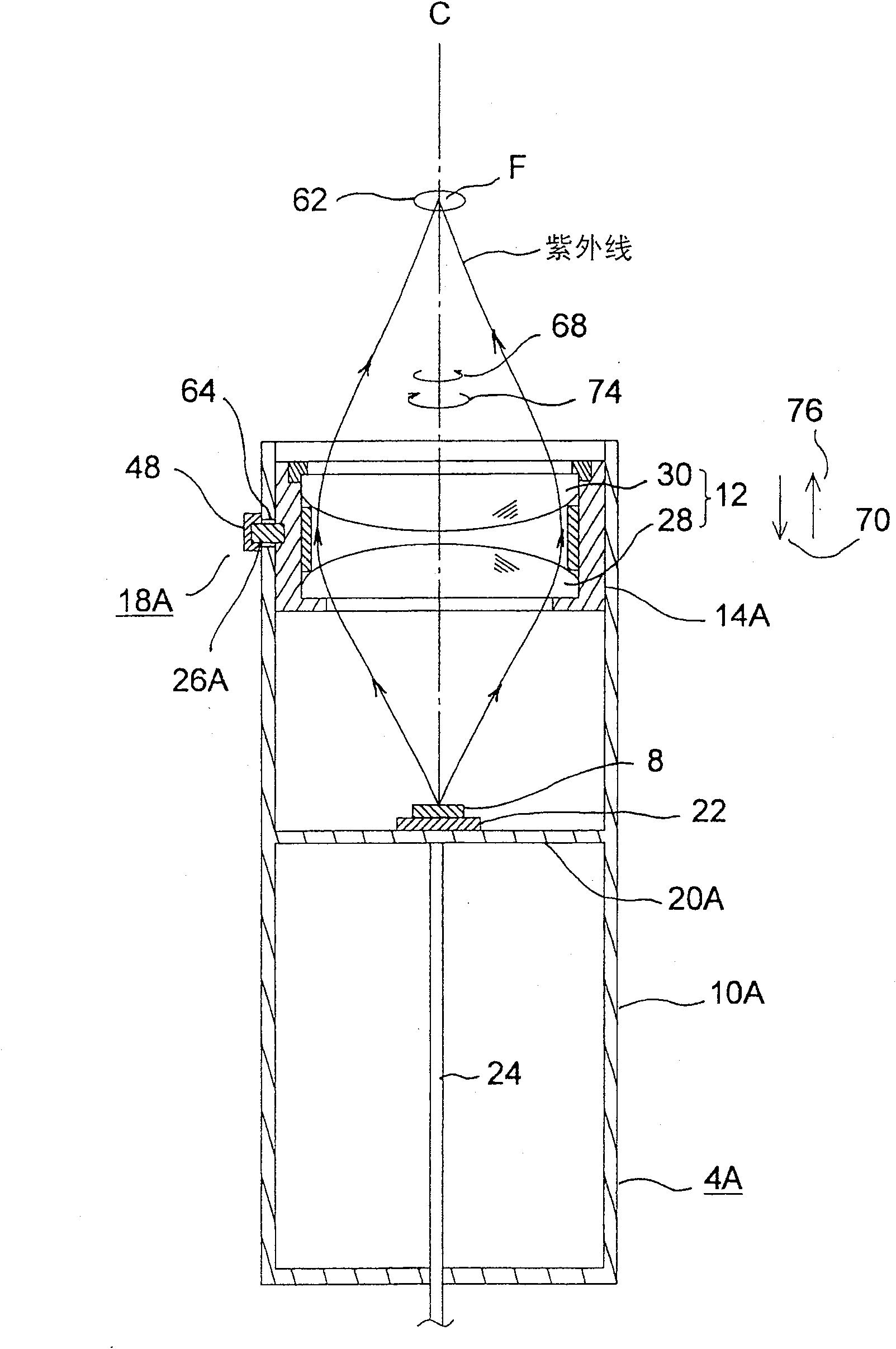
[0058] Next, refer to image 3 and Figure 4 , to illustrate the head of the second embodiment of the present invention. image 3 is a schematic sectional view showing the head, Figure 4 yes means image 3 A schematic diagram of the separation distance adjustment mechanism and its surrounding structures. In addition, in the following embodiment, the same code|symbol is attached|subjected to the same component as 1st Embodiment in embodiment, and the description is abbreviate|omitted.
[0059] The head portion 4A of the second embodiment is not provided with a cylindrical outer body as in the first embodiment, and the first mounting mechanism 10A is configured as a cylindrical body, and a mounting wall 20A is provided inside the axially intermediate portion thereof. The wiring board 22 on which the light emitting diode 8 is actually mounted is mounted on the central portion of one side of the mounting wall 20A. In addition, a guide hole 64 extending obliquely in the circumf...
no. 3 approach
[0064] Next, refer to Figure 5 and Image 6 A head section according to a third embodiment of the present invention will be described. Figure 5 is a schematic sectional view showing the head, Image 6 yes means Figure 5 A schematic diagram of the regulatory ring and its surrounding structures.
[0065] In the head part 4B of the third embodiment, the second mounting mechanism 14B is configured as a cylindrical body, and the condensing lens 12 is mounted inside on the one end side thereof. The bottom plate member 98 is mounted on the other end of the second mounting mechanism 14B, and the first mounting mechanism 10B is mounted inside the other end side of the second mounting mechanism 14B. The axis can move freely. A pin 26B extending radially outward is provided on the outer portion of the first mounting mechanism 10B, and a first guide hole extending linearly in the axial direction of the second mounting mechanism 14B is provided on the second mounting mechanism 14B....
PUM
 Abstract
Description
Claims
Application Information
 - R&D
- Intellectual Property
- Life Sciences
- Materials
- Tech Scout
- Unparalleled Data Quality
- Higher Quality Content
- 60% Fewer Hallucinations
Browse by: Latest US Patents, China's latest patents, Technical Efficacy Thesaurus, Application Domain, Technology Topic, Popular Technical Reports.
© 2025 PatSnap. All rights reserved.Legal|Privacy policy|Modern Slavery Act Transparency Statement|Sitemap|About US| Contact US: help@patsnap.com


