Method for coating LED excited fluorescence powder

A technology of LED light source and phosphor powder, which is applied in the direction of coating, device for coating liquid on the surface, electrical components, etc., can solve the problems of increasing the thickness of the backlight source, which is not conducive to the production of the backlight source, and achieves good stability and light mixing. Uniform, precise color control results

Inactive Publication Date: 2009-09-23
SUN YAT SEN UNIV
View PDF11 Cites 0 Cited by
  • Summary
  • Abstract
  • Description
  • Claims
  • Application Information

AI Technical Summary

Problems solved by technology

In addition, in the patent US7036946-B1, a side-firing UV LED combined with a waveguide structure is used to excite the phosphor screen with ultraviolet light. The LCD backlight adopts an LED side-firing structure, which increases the thickness of the backlight. Radial structure is not conducive to the production of large-area backlight

Method used


Image

  • Method for coating LED excited fluorescence powder
  • Method for coating LED excited fluorescence powder
  • Method for coating LED excited fluorescence powder

Examples


Embodiment 1

[0024] Select a transparent ceramic plate 2 with good thermal conductivity, and use mechanical processing, chemical corrosion or sintering to make a cuboid phosphor filling hole 3, and fill the YAG phosphor 4 directly into the phosphor filling by methods such as filling, depositing, sintering or vapor deposition. In the hole 3, it is directly packaged into a flat phosphor screen structure, and then packaged into a single-chip white LED ( Figure 5 ) or multi-chip white LED ( Image 6 ).

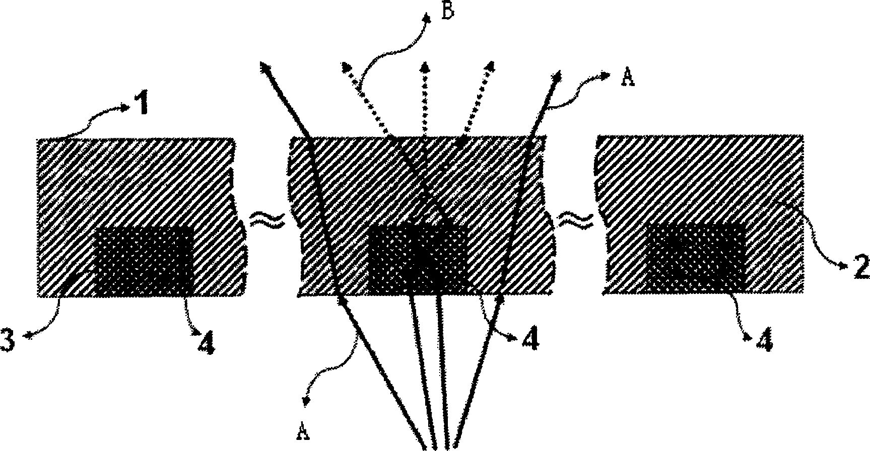
[0025] Since the LED is excited with uniform light intensity, according to the light field distribution, phosphors with uniform depth, uniform size and uniform arrangement are used to fill the holes ( figure 1 a). Such as figure 2 As shown, part of the blue light A excited by the LED is excited by YAG phosphor to produce yellow-green light B, and the other part passes through the area without phosphor to reach the outside, which is still blue light A, and some colors are mixed to form whi...

Embodiment 2

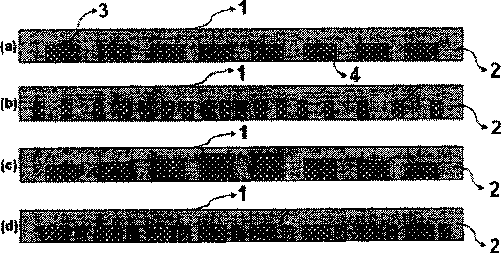
[0028] For LEDs with non-uniform light intensity, according to the distribution of the light field, the arrangement of phosphor powder filled holes 3 can adopt an arrangement of uniform depth, uniform width, and uneven arrangement ( figure 1 b); or use an arrangement with inconsistent depth, uniform width, and uniform arrangement ( figure 1 c); or adopt an arrangement method with consistent depth, inconsistent width, and uniform arrangement ( figure 1 d). Color control is achieved through this arrangement.

Embodiment 3

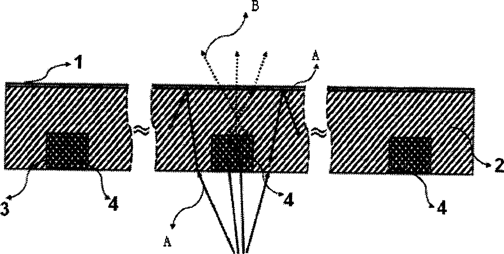
[0030] In order to be used for ultraviolet LED excitation, a layer of ultraviolet reflection film (1) can also be coated on the upper part of the fluorescent powder screen, so as to avoid the leakage of ultraviolet light in the device. The reflected UV light is either absorbed or re-excited. See image 3 .


PUM


Abstract

The present invention is method of coating LED excited fluorescence powder. Fluorescence powder is filled into the LED exciting screen to form the fluorescence screen device, and through regulating the shape, size and arrangement of the cavity for filling fluorescence powder and selecting fluorescence powder, the fluorescence color may be controlled. The present invention has precise fluorescence color control, homogeneous color mixing and high performance stability, and may have single LED chip or multiple LED chips in the fluorescence screen structure. The present invention may be used in different display fields with high color quality requirement, such as street lamp, vehicle lamp, miner's lamp, etc.

Description

technical field [0001] The invention relates to the field of LED excitation phosphors, in particular to a phosphor coating method for LED excitation. Background technique [0002] LED is a semiconductor light-emitting device, which is widely used in lighting or display fields such as indicator lights and display screens. White LED is known as the fourth-generation lighting source to replace fluorescent lamps and incandescent lamps. A traditional way to form a white light LED is that a blue light or ultraviolet chip excites the phosphor powder covered on the chip, and the light emitted by the chip under electric drive stimulates the phosphor powder to produce visible light in other bands, and each part mixes colors to form white light. [0003] The LED chips that generate white light by phosphor excitation are made of III-V compound semiconductor GaN materials. Among them, the substrate material used for GaN chip is Al 2 o 3 And SiC, the chip can emit blue light, ultravio...

Claims


Application Information

Patent Timeline
Patent Type & Authority Patents(China)
IPC IPC(8): B05D7/00B05D7/24H01L33/00
Inventor 王钢范冰丰
Owner SUN YAT SEN UNIV
Why Eureka
Try Eureka