Plastic surface vacuum plating process

A technology for vacuum coating and plastic parts, applied in vacuum evaporation coating, surface pretreatment, metal material coating process, etc., can solve the problems of restricting the safe use of plastic parts, semi-mirror effect that the film layer does not have a metallic texture, etc. The effect of achieving good insulation effect

Inactive Publication Date: 2009-08-19
MITAC PRECISION TECH CO LTD SHUNDE DISTRICT FOSHAN CITY
View PDF5 Cites 0 Cited by
  • Summary
  • Abstract
  • Description
  • Claims
  • Application Information

AI Technical Summary

Problems solved by technology

Traditional coating methods include: (1) Coating aluminum, nickel or chromium metal films on transparent plastic parts by vacuum sputtering to obtain plastic parts with metallic luster and semi-mirror effect, but because the film is a metal film However, it is conductive, which limits the safe use of plastic parts
(2) The electron gun vacuum evaporation coating method is used to coat the surface of plastic parts with SiO 2 / TiO 2 The transparent film with high and low refractive index composed of equal components forms a semi-transparent effect with color by optical action, but the film layer obtained by this method does not have the semi-mirror effect of metallic texture

Method used


Image

  • Plastic surface vacuum plating process

Examples


Embodiment 1

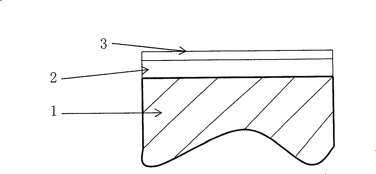
[0023] After cleaning the surface of the PC plastic part 1 by ultrasonic cleaning, spray a layer of UV primer 2 for vacuum sputtering, control the thickness of the paint layer to 5-20 μm, and then cure it under ultraviolet light; use zirconium metal as the target material for vacuum Sputtering, the sputtering process conditions are: coating power 9Kw, Ar flow rate 140Sccm, N 2 The flow rate is 65Sccm, and the coating time is 5 seconds. A zirconium nitride coating 3 with a film thickness of 10-30 nm was obtained. The coating had a metallic color and a semi-mirror texture, and its resistance value was determined to be infinite.

Embodiment 2

[0025] After cleaning the surface of the PC plastic part 1 by ultrasonic cleaning, spray a layer of UV primer 2 for vacuum sputtering, control the thickness of the paint layer to 5-20 μm, and then cure it under ultraviolet light; use zirconium metal as the target material for vacuum Sputtering, the sputtering process conditions are: coating power 9Kw, Ar flow rate 140Sccm, N 2 The flow rate is 150Sccm, and the coating time is 5 seconds. A zirconium nitride coating 3 with a film thickness of 10-30 nm was obtained. The coating had a metallic color and a semi-mirror texture, and its resistance value was determined to be infinite.

Embodiment 3

[0027] After cleaning the surface of the PC plastic part 1 by ultrasonic cleaning, a layer of primer layer 2 with a thickness of 5-20 μm is coated on the surface by immersion plating, and then cured by ultraviolet light; zirconium metal is used as the target material. Vacuum sputtering, the sputtering process conditions are: coating power 9Kw, Ar flow rate 140Sccm, N 2 The flow rate is 70Sccm, and the coating time is 5 seconds. A zirconium nitride coating 3 with a film thickness of 40-70 nm was obtained. The coating had a metallic color and a semi-mirror texture, and its resistance value was determined to be infinite.


PUM

PropertyMeasurementUnit
thicknessaaaaaaaaaa
thicknessaaaaaaaaaa
thicknessaaaaaaaaaa

Abstract

The invention relates to a vacuum coating process on the surface of plastic parts. The process steps are: ultrasonically clean the surface of the plastic part to be plated, and then apply a layer of bottom coating with a thickness of 5-20 μm on the surface of the plastic part, and then cure it by ultraviolet light. , and finally use zirconium metal as the target material to carry out vacuum sputtering under the conditions of argon gas flow rate of 140Sccm, coating power of 2-9Kw, coating time of 3-5 seconds, and nitrogen flow rate greater than or equal to 50Sccm, to obtain a reactive sputtering layer with a thickness of 10-70nm. Coated zirconium nitride film. The film layer plated on the surface of the plastic part through the process of the invention has a semi-mirror luster texture and good insulation effect.

Description

technical field [0001] The invention relates to a coating process on the surface of plastic parts, more specifically, to a vacuum coating process on the surface of plastic parts. Background technique [0002] Plastic parts are used more and more widely in daily life. In order to beautify the surface appearance of plastic parts, the surface of plastic parts is usually coated with a film, especially a film with a semi-mirror glossy texture. The traditional coating methods are: (1) Coating aluminum, nickel or chromium metal films on transparent plastic parts by vacuum sputtering to obtain plastic parts with metallic luster and semi-mirror effect, but because the film is a metal film However, it is conductive, which limits the safe use of plastic parts. (2) The electron gun vacuum evaporation coating method is used to coat the surface of plastic parts with SiO 2 / TiO 2 The transparent film with high and low refractive index composed of the same composition can form a semi-tra...

Claims


Application Information

Patent Timeline
Patent Type & Authority Patents(China)
IPC IPC(8): C23C14/02C23C14/12C23C14/54B08B3/12B05B3/00B05B5/00B05D3/06
Inventor 林壮坤
Owner MITAC PRECISION TECH CO LTD SHUNDE DISTRICT FOSHAN CITY
Why Eureka
Try Eureka